Direct-current vehicle traction system

A vehicle traction and differential current technology, which is applied in electric traction, vehicle components, electric braking systems, etc., can solve problems such as elevation, energy cannot flow in both directions, and threaten equipment safety, so as to achieve stable system operation and avoid electromagnetic interference , the effect of suppressing harmonics

Inactive Publication Date: 2016-12-21
XIAN UNIV OF SCI & TECH
View PDF4 Cites 7 Cited by
  • Summary
  • Abstract
  • Description
  • Claims
  • Application Information

AI Technical Summary

Problems solved by technology

[0004] The embodiment of the present invention provides a DC vehicle traction system, which is used to solve the problems that the existing DC vehicle traction system adopts the DC grid, the energy cannot flow in both directions, and the voltage of the DC grid is raised during the regenerative braking of the vehicle, which threatens the safety of the equipment.

Method used


Image

  • Direct-current vehicle traction system
  • Direct-current vehicle traction system

Examples


Embodiment Construction

[0030] The following will clearly and completely describe the technical solutions in the embodiments of the present invention with reference to the accompanying drawings in the embodiments of the present invention. Obviously, the described embodiments are only some, not all, embodiments of the present invention. Based on the embodiments of the present invention, all other embodiments obtained by persons of ordinary skill in the art without making creative efforts belong to the protection scope of the present invention.

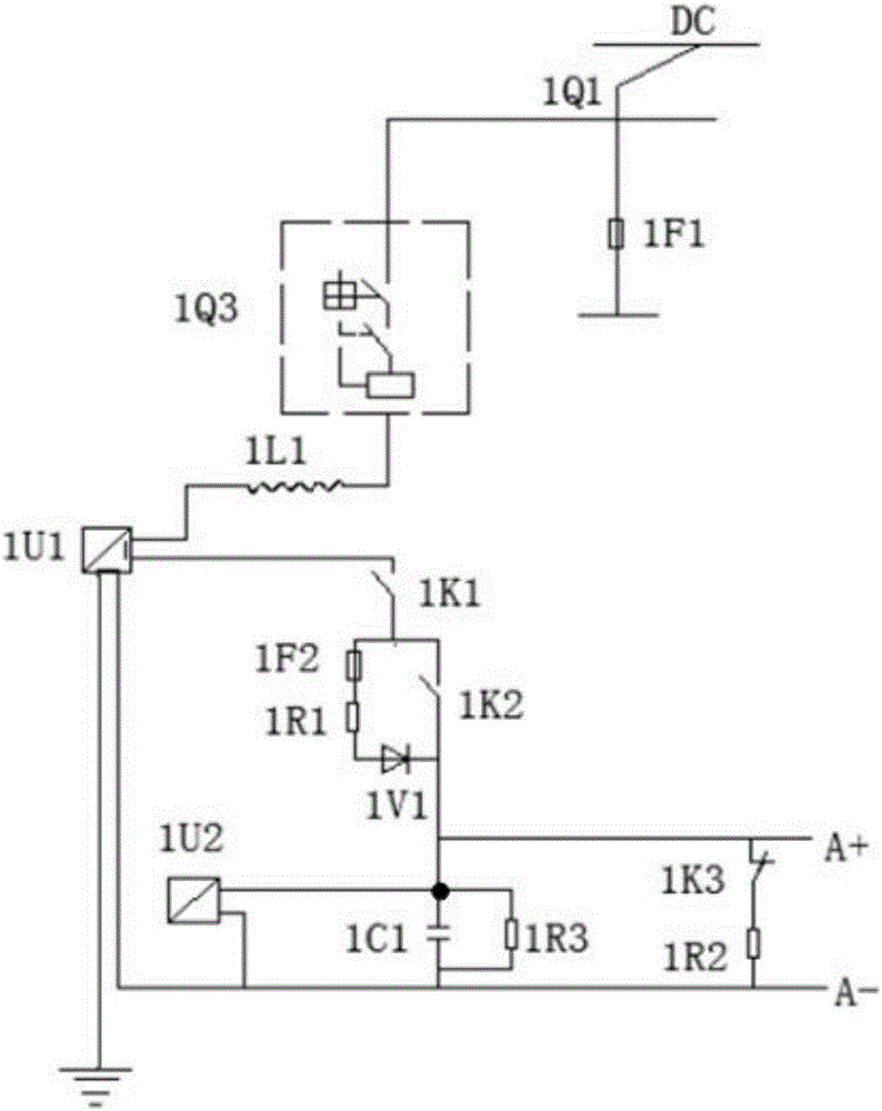
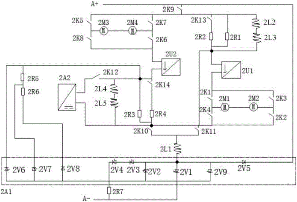
[0031] figure 1 It exemplarily shows a schematic diagram of a filter circuit of a DC vehicle traction system provided by an embodiment of the present invention; figure 2 It is a schematic diagram of a traction braking circuit of a DC vehicle traction system provided by an embodiment of the present invention. Such as figure 1 and figure 2 As shown, a DC vehicle traction system provided by an embodiment of the present invention includes: a filter circuit, a...


PUM


Abstract

The invention discloses a direct-current vehicle traction system and relates to the technical field of traction power. The direct-current vehicle traction system is used for solving the problems that in the prior art, energy cannot flow in a bidirectional mode, and the equipment safety is threatened due to the fact that the voltage of a direct-current electric network is increased during vehicle regenerative braking. The direct-current vehicle traction system comprises a filter circuit, a traction braking circuit and a processor. The traction braking circuit comprises a power supply input positive pole A+ end which is sequentially connected with a first brake resistor, a first current transformer, a first motor device, a second traction contactor, a first inductor and a first GTO thyristor in series through a first traction contactor, finally, the power supply input positive pole A+ end is connected to a power supply input negative pole A- end, and the first inductor is connected with the positive pole of the first GTO thyristor; the power supply input positive pole A+ end is sequentially connected with a second motor device, a second current transformer, a second brake resistor, a second traction contactor, the first inductor and the first GTO thyristor in series through the first traction contactor; and the contactors, a current sensor, a voltage sensor and the thyristor are all connected with the processor.

Description

technical field [0001] The invention relates to the technical field of traction power, and more specifically relates to a DC vehicle traction system. Background technique [0002] With the rapid development of the national economy, urban traffic problems have become increasingly prominent. The development of urban rail transit systems represented by subways is the only way to solve urban traffic problems. At present, urban rail transit traction grids use DC grids rectified by diodes. Two-way flow; and the operating characteristics of urban rail transit vehicles are: frequent startup acceleration, frequent braking and deceleration, the electric energy generated during vehicle regenerative braking will increase the DC grid voltage and threaten the safety of equipment. [0003] To sum up, the existing DC vehicle traction system adopts the DC grid, and there are problems that the energy cannot flow in both directions, and the voltage of the DC grid is raised during the regenerat...

Claims


Application Information

Patent Timeline
Patent Type & Authority Applications(China)
IPC IPC(8): B60L9/00B60L15/20B60L7/10B60M7/00B60M3/06
CPCB60L7/10B60L9/00B60L15/20B60M3/06B60M7/00B60L2240/421Y02T10/72
Inventor 崔江霞
Owner XIAN UNIV OF SCI & TECH
Why Eureka
Try Eureka