[0021] By referring to exemplary embodiments, the objects and functions of the present invention and the methods for achieving these objects and functions will be clarified. However, the present invention is not limited to the exemplary embodiments disclosed below; it can be implemented in different forms. The essence of the description is only to help those skilled in the relevant art to comprehensively understand the specific details of the present invention.
[0022] Hereinafter, embodiments of the present invention will be described with reference to the drawings. In the drawings, the same reference signs represent the same or similar parts or the same or similar steps.
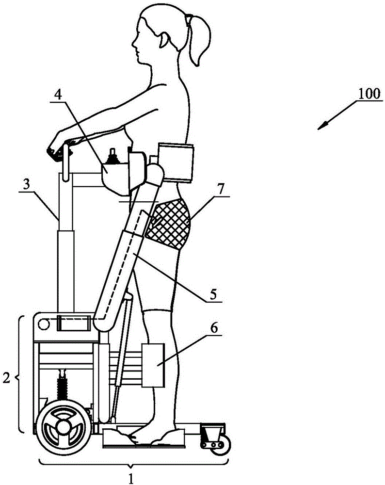
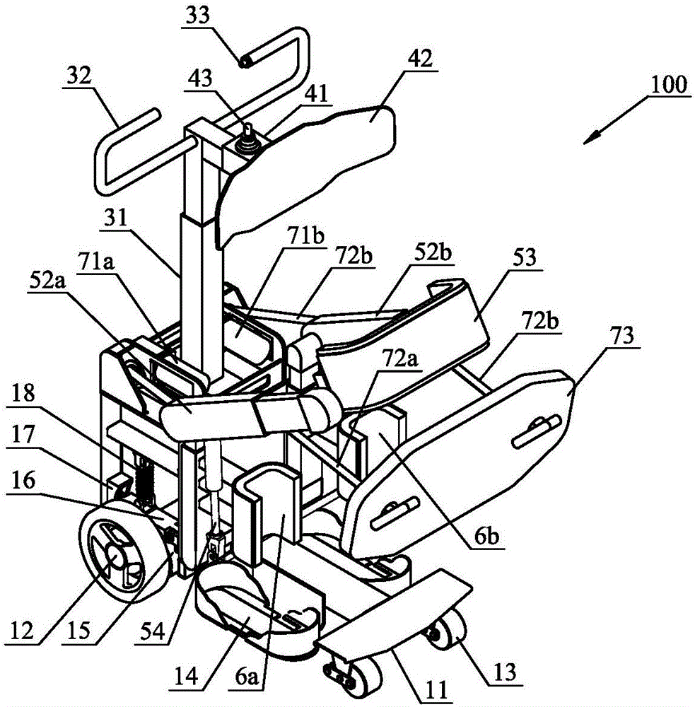
[0023] figure 1 with figure 2 A schematic diagram and a three-dimensional structure diagram of a scooter 100 for the disabled according to the present invention are shown during driving. The scooter 100 of the present invention includes: a chassis walking mechanism 1, a fixed bracket 2, an armrest mechanism 3, a chest and abdomen support mechanism 4, a lumbar support mechanism 5, a knee support mechanism 6, and a hip support mechanism 7. The object of use is mainly disabled persons, such as People with leg disabilities or paralyzed lower body.
[0024] The chassis running mechanism 1 is located at the bottom of the scooter 100 and is mainly used to carry the user and drive the scooter 100 to move forward. The scooter 100 includes a bottom plate 11, a front wheel assembly 12, a rear wheel assembly 13, a pedal 14 and a first driving mechanism 15 that drives the chassis traveling mechanism 1 to travel. The footboard 14 is located on both sides of the middle part of the bottom plate 11, and the footboard 14 is provided with ring-shaped blocking pieces at the front and back to prevent the user's feet from sliding greatly, and achieve the purpose of fixing the user's feet.
[0025] A front wheel assembly 12 and a rear wheel assembly 13 are respectively provided at the front and rear bottom of the bottom plate 11. The front wheel assembly 12 is a driving wheel and the driving power is provided by the first drive mechanism 15 located in the front of the bottom plate 11, and the rear wheel assembly 13 is a driven wheel and Preferably, a universal wheel assembly is used. The front wheel assembly 12 is also provided with a shock-absorbing arm 16, a shock-absorbing groove 17, and a shock-absorbing damping 18. Similarly, the rear wheel assembly 13 can also be provided with a corresponding shock-absorbing device, thereby effectively reducing the driving process of the scooter 100 The intensity of the vibration generated in the battery ensures the safety of the user and increases the driving comfort of the user.
[0026] The fixing bracket 2 is located above the front part of the bottom plate 11 and is a steel frame structure, and its bottom is fixedly connected to the bottom plate 11, and is mainly used to fix the first driving mechanism 15, the shock-absorbing arm 16, the shock-absorbing groove 17 and the shock-absorbing damping 18 Wait.
[0027] The armrest mechanism 3 is located directly above the fixed bracket 2, and its bottom is fixedly connected to the upper center of the fixed bracket 2 and arranged vertically upwards. It mainly includes a telescopic rod 31, a handle 32 at the upper end of the telescopic rod 31, and a handle 32 at the end The second driving mechanism controller 33. The telescopic rod 31 is a two-level rod or a multi-level rod structure, which can be freely extended and self-locked, and can be adjusted according to the height of the user during use.
[0028] The chest and abdomen support mechanism 4 is located directly in front of the user's chest or abdomen, and is used to support the user's chest or abdomen, prevent the user from falling forward, and help the user stand stably and achieve long-term standing. The chest and abdomen support mechanism 4 mainly includes a connecting rod 41, a chest and abdomen support plate 42 and an integrated controller 43 for controlling the first drive mechanism 15, the third drive mechanism 71a, and the fourth drive mechanism 71b. The connecting rod 41 is arranged horizontally, one end of which is vertically connected to the upper end of the telescopic rod 31, and the other end is connected with the chest and abdomen support plate 42; the upper surface of the connecting rod 41 is also provided with a first driving mechanism controller 43, which is The controller 43 controls the first driving mechanism 15 to realize the start, stop, and speed change of the scooter 100. The chest and abdomen support plate 42 presents an arc-shaped plate structure that matches the chest or abdomen of the user, and its surface is provided with soft shock-absorbing materials, thereby improving the comfort of the chest or abdomen of the user.
[0029] The back support mechanism 5 is used to support the waist or back of the user to prevent the user from falling backward. Such as image 3 As shown, the back support mechanism 5 mainly includes a first swing arm frame 51a, a second swing arm frame 51b, a first telescopic swing arm 52a and a second swing arm movably connected to the first swing arm frame 51a and the second swing arm frame 51b, respectively. Two telescopic swing arms 52b, waist protection 53, and second driving mechanism 54.
[0030] The first swing arm frame 51a and the second swing arm frame 51b are hollow two-stage rod structures with telescopic self-locking function, and are respectively vertically arranged on both sides of the middle of the bottom plate 11 and close to the fixed bracket 2. The bottoms of the first swing arm bracket 51 a and the second swing arm bracket 51 b are fixed on the bottom plate 11, and the side surfaces are fixed by the fixing bracket 2. One end or fulcrum end of the first telescopic swing arm 52a is movably connected to the upper end of the first swing arm frame 51a, and the other end is connected to one end of the waist guard 53; similarly, one end of the second telescopic swing arm 52b is connected to the second swing arm The upper end of the frame 51b is movably connected, and the other end is connected to the other end of the waist guard 53. The first telescopic swing arm 52a and the second telescopic swing arm 52b are both two-stage rod structures, which can be retracted and self-locked. The waist protector 53 is connected to the buckle grooves provided on the rotating shafts at the ends of the first telescopic swing arm 52a and the second telescopic swing arm 52b through buckles at both ends, and the buckles are detachably connected to the buckle grooves.
[0031] The second driving mechanism 54 is used to drive the first telescopic swing arm 52a and the second telescopic swing arm 52b to swing up and down. Specifically, the second driving mechanism 54 includes a first linear driver 54a that drives the first telescopic swing arm 52a to swing up and down, and a second linear driver 54b that drives the second telescopic swing arm 52b to swing up and down. The fixed ends of the first linear driver 54a and the second linear driver 54b are both movably connected to the fixed bracket 2, and their moving ends are respectively movably connected to the middle of the first telescopic swing arm 52a and the second telescopic swing arm 52b. The first linear driver 54a and the second linear driver 54b preferably adopt electric push rods.
[0032] The first linear driver 54a and the second linear driver 54b simultaneously push the first telescopic swing arm 52a and the second telescopic swing arm 52b to move up and down around the fulcrum end, thereby driving the waist guard 53 to move up and down together, and further pass the waist guard 53 exercises to assist the user to get up and stand, and at the same time, the waist protector 53 can also rotate flexibly following the movement of the user's upper body.
[0033] The knee support mechanism 6 includes a first knee support 6a and a second knee support 6b in the shape of a "U" groove, which are respectively fixed on the secondary rods of the first telescopic swing arm 52a and the second telescopic swing arm 52b. It can be adjusted up and down according to the extension and contraction of the secondary rods of the first telescopic swing arm 52a and the second telescopic swing arm 52b, so that the height of the knee support mechanism 6 can also be adjusted according to the height of the user's knee or calf. The knee support mechanism 6 is mainly used to prevent bending of the knee and assist the user's calf to achieve standing.
[0034] The buttocks support mechanism 7 includes a third drive mechanism 71a, a fourth drive mechanism 71b, a first binding belt 72a, a second binding belt 72b, and a buttocks support pad 73. The third drive mechanism 71a and the fourth drive mechanism 71b are respectively fixed on both sides of the upper part of the fixed bracket. One end of the first binding belt 72a is connected with the third drive mechanism 71a, and the other end passes through the fulcrum end of the first telescopic swing arm 52a. Enter and pass through the opening provided on the secondary rod of the first telescopic swing arm 52a, and movably connect with one end of the buttocks support cushion 73 after passing through; similarly, one end of the first binding strap 72b is connected to the fourth driving mechanism 71b. Connected, the other end penetrates through the fulcrum end of the second telescopic swing arm 52b and exits through the opening provided on the secondary rod of the second telescopic swing arm 52b, and is movably connected to the other end of the buttocks support cushion 73 after passing out.
[0035] Preferably, the first binding belt 72a and the buttocks support cushion 73 are connected by a buckle, that is, the end of the first binding belt 72a is provided with a buckle, and the buckle is buckled in the buckle groove at one end of the buttocks support cushion 73 to form a detachable connection ; Similarly, the second binding belt 72b and the buttocks support cushion 73 are connected by a buckle, that is, the end of the second binding belt 72b is provided with a buckle, and the buckle is buckled in the buckle groove at the other end of the buttocks support cushion 73 to form a Disconnect the connection.
[0036] More preferably, the first binding strap 72a and the buttocks support pad 73 are connected by a turn buckle, that is, the end of the first binding strap 72a is tied with a turn buckle, and the turn buckle is buckled in the turn button hole at one end of the buttocks support pad 73 to form a detachable Movable connection; Similarly, the second binding strap 72b and the buttocks support pad 73 are connected by a turnbuckle, that is, the end of the second binding strap 72b is tied with a turnbuckle, and the turnbuckle is buckled in the turnbuckle hole at the other end of the buttocks support pad 73, Form a detachable movable connection.
[0037] The third driving mechanism 71a and the fourth driving mechanism 71b respectively drive the first binding belt 72a and the second binding belt 72b to tighten or relax the buttocks support cushion 73, so that the buttocks support cushion 73 can support the user's buttocks and further stabilize This improves the user’s standing posture, prevents the user from squatting, and also improves the user’s comfort.
[0038] Such as Figure 4 As shown, the user can operate the scooter 100 to switch between sitting and standing positions. When the user needs to operate the scooter 100 of the present invention to switch from a sitting position to a standing position, the user first removes the waist guard 53 and buttocks The support pad 73 is then placed under the buttocks and the waist support 53 is connected to the ends of the first telescopic swing arm 52a and the second telescopic swing arm 52b from behind the waist.
[0039] Secondly, the user puts his feet on the footrest 14 while twisting the integrated controller 43 to control the third driving mechanism 71a and the fourth driving mechanism 71b to reverse, thereby shortening the first binding belt 72a and the second binding belt 72b to Place the hip support pad 73 close to the user’s buttocks, and then close the calf or knee to the "U"-shaped grooves of the first knee support 6a and the second knee support 6b, while the user grasps the handle with his hand 32.
[0040] Finally, the user presses the second drive mechanism controller 33 with his right thumb to control the second drive mechanism 54 to push the "T"-shaped transmission shaft 54b to rotate and drive the first telescopic swing arm 52a and the second telescopic swing arm 52b to swing upwards. The arm movement simultaneously drives the waist guard 53 and the buttocks support cushion 73 to support the user’s waist and buttocks, thereby completing the user’s transition from a sitting state to a standing posture and can continue to maintain a standing state, and further the user can use the integrated controller 43. Control the first driving mechanism 15 to drive the front wheel assembly 12 to make the scooter 100 of the present invention walk forward. The user can drive the scooter 100 to achieve forward, backward and turning operations. In addition, the first drive of the scooter 100 of the present invention The mechanism 15, the second drive mechanism 54, the third drive mechanism 71a, and the fourth drive mechanism 71b can all realize the self-locking function when in the stopped state, thereby effectively ensuring the personal safety of the user.
[0041] When the user is not using the scooter 100, he only needs to press the second driving mechanism controller 33 with his right thumb to control the first telescopic swing arm 52a and the second telescopic swing arm 52b to produce downward swinging arm movement, and at the same time under the weight of the body Under compression, the first telescopic swing arm 52a and the second telescopic swing arm 52b are gradually shortened, and the waist guard 53 and the buttocks support cushion 73 will also slowly swing downwards, and the end user will slowly change from standing to sitting and from standing. Just release your right thumb after sitting. Furthermore, the integrated controller 43 can be twisted to control the third drive mechanism 71a and the fourth drive mechanism 71b to rotate forward so that the buttocks support pad 73 is in a relaxed state so that the buttocks support pad 73 can be removed, and then the waist support 53 is removed and the calf is removed If the board 14 is taken off, the scooter 100 can be separated.
[0042] In summary, the user driving the scooter 100 of the present invention can switch between sitting and standing positions at will, and the user can complete daily activities such as cooking, dining, and going to the toilet on the scooter 100 to realize self-care . After being fixed on the scooter 100, the user can also use the auxiliary standing mechanism to repeatedly sit and stand to perform simple rehabilitation squatting training for the legs. Finally, a scooter 100 for the disabled of the present invention has the advantages of ingenious design, compact structure, simple operation, safety and stability.
[0043] The drawings described are only schematic and are not drawn to scale. Although the present invention has been described in conjunction with preferred embodiments, it should be understood that the protection scope of the present invention is not limited to the embodiments described herein.
[0044] In combination with the description and practice of the present invention disclosed herein, other embodiments of the present invention are easily thought of and understood by those skilled in the art. The description and embodiments are only considered to be exemplary, and the true scope and spirit of the present invention are defined by the claims.