Height-adjustable outboard motor hanging rack

A high-level technology for outboard motors, applied in ship propulsion, ship parts, ship construction, etc., can solve problems such as waste of resources, damage to propellers, rising of outboard motors, etc., and achieve the effects of convenient storage, reliable connection, and flexible disassembly

Active Publication Date: 2016-12-21
CHINA HARZONE IND CORP
View PDF5 Cites 3 Cited by
  • Summary
  • Abstract
  • Description
  • Claims
  • Application Information

AI Technical Summary

Problems solved by technology

[0003] 1. The fixed outboard motor hanger, as a part of the engineering buoy, is directly welded on the buoy and cannot be disassembled, so the outboard can only be hung on the side of the hanger mechanism of the engineering buoy, so the power of the buoy The direction of propulsion is fixed to one side of the pontoon. When the pontoon needs power in different propulsion directions, it is necessary to redesign and manufacture the pontoon, resulting in a waste of resources.
[0004] 2. When the water level of the river changes and encounters a shoal, the outboard motor cannot dodge in time, then the propeller of the outboard motor will touch the river bed, causing damage to the propeller and loss of propulsion ability
[0005] 3. The draught of the engineering buoyancy tank varies greatly from empty load to full load. If the outboard motor hanger mechanism is set according to the empty load, then, in order to ensure that the outboard motor propeller has sufficient draft, the hanger mechanism needs to be set at the bottom of the buoyancy tank. Lower position, in this way, when the pontoon is loaded, the pontoon sinks, the pylon mechanism sinks accordingly, and the draft of the propeller of the outboard motor increases. When the pylon sinks a lot, the engine of the outboard motor will Submerged in t

Method used


Image

  • Height-adjustable outboard motor hanging rack
  • Height-adjustable outboard motor hanging rack
  • Height-adjustable outboard motor hanging rack

Examples


Embodiment Construction

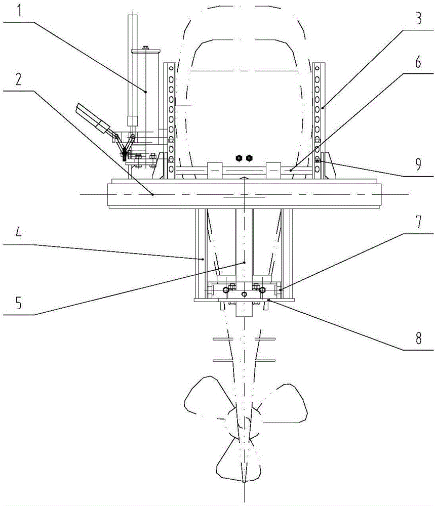
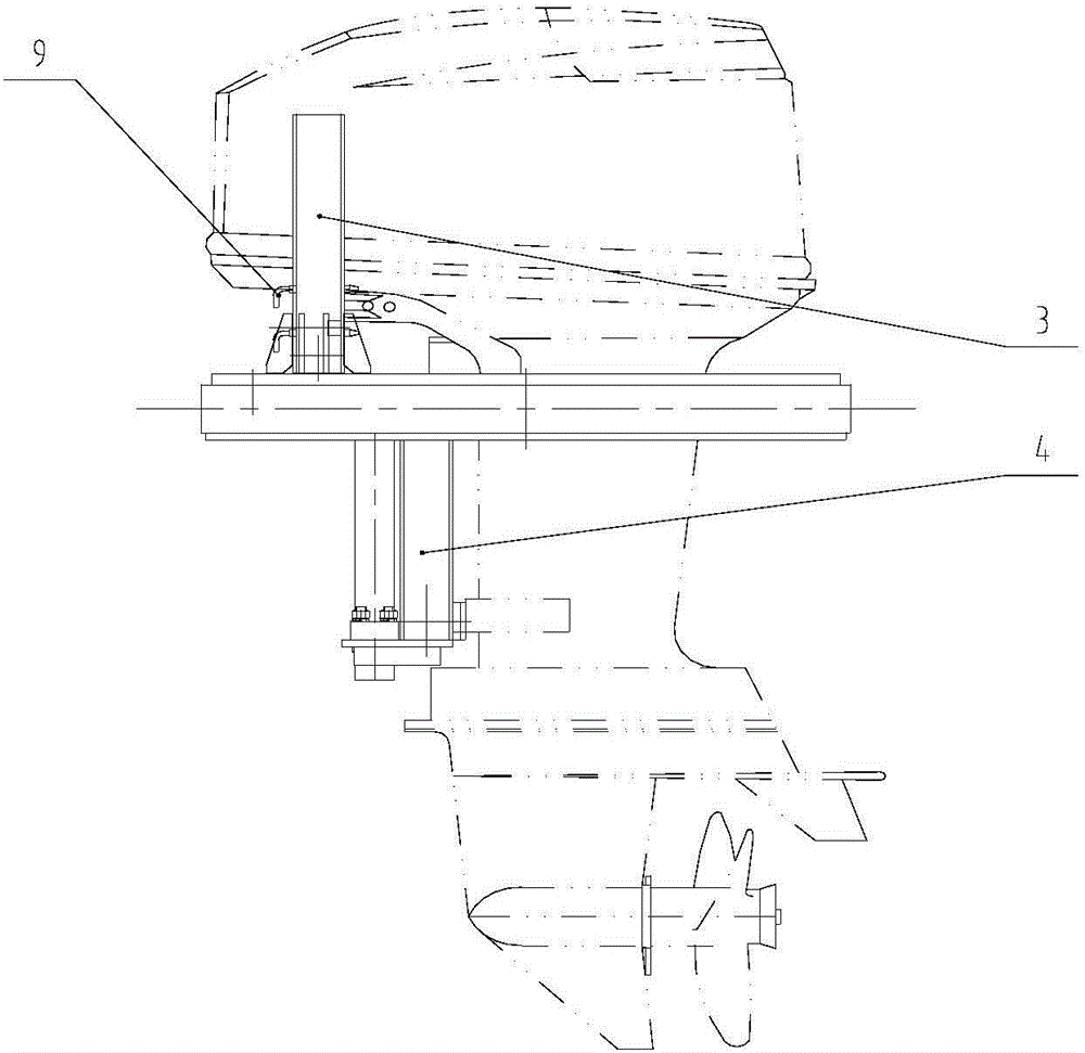
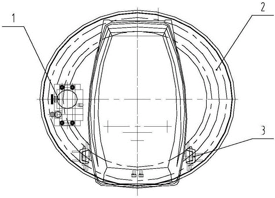
[0020] See attached Figure 1-4 , a height-adjustable outboard motor hanger, which includes: hand pump 1, platform 2, upper guide rail 3, lower guide rail 4, oil cylinder 5 driven by hand pump 1, upper roller assembly 6, lower roller assembly Assembly 7, oil cylinder mount 8;

[0021] The center of the platform 2 accommodates the outboard motor. The hand pump 1 used to drive the piston rod 10 of the oil cylinder 5 to reciprocate is installed on one side of the outboard motor on the upper part of the platform 2. The section of the upper guide rail 3 is a groove structure, which is welded vertically and symmetrically. On both sides of the outboard motor on the upper part of the platform 2; the section of the lower guide rail 4 is a groove structure, welded on both sides of the outboard motor on the lower part of the platform 2 and parallel to the upper guide rail 3, and the oil cylinder mounting seat 8 is welded on the bottom of the lower guide rail 4, and The lower guide rail ...


PUM


Abstract

The invention belongs to the technical field of engineering pontoons and particularly relates to an outboard motor hanging rack. According to the technical scheme, the height-adjustable outboard motor hanging rack comprises a hand pump, a platform, upper guide rails, lower guide rails, an oil cylinder driven by the hand pump, an upper roller assembly, a lower roller assembly and an oil cylinder mounting seat; when the water level gets lower, the hand pump is operated, a piston rod of the oil cylinder is enabled to jack up an outboard motor to ascend to appropriate height; when the water level gets higher, the hand pump is reversely operated, the piston rod of the oil cylinder is enabled to descend, the outboard motor downwards slides to appropriate height along the upper guide rails and the lower guide rails under the action of gravity, and a propeller is enabled to keep appropriate draft. The height-adjustable outboard motor hanging rack can be used for adjusting the draft of the propeller of the outboard motor conveniently, thereby adapting to the water depth of a river channel and also adapting to larger draft change in loading and unloading processes of the pontoons.

Description

technical field [0001] The invention belongs to the technical field of engineering buoyancy tanks, in particular to a hanger for an outboard engine. Background technique [0002] When the engineering buoy needs to be equipped with power, the outboard motor with high system integration, simple installation process and low installation technical requirements is usually used. The outboard motor is installed on the outboard motor hanger of the engineering buoyancy tank. The existing buoyant tank outboard motor hanger is in the form of a fixed type, which is welded together with the buoyancy tank and cannot be disassembled. This method has the following disadvantages: [0003] 1. The fixed outboard motor hanger, as a part of the engineering buoy, is directly welded on the buoy and cannot be disassembled, so the outboard can only be hung on the side of the hanger mechanism of the engineering buoy, so the power of the buoy The direction of propulsion is just fixed as a side of the...

Claims


Application Information

Patent Timeline
IPC IPC(8): B63H20/10
CPCB63B2747/02B63H20/106
Inventor 史生凤
Owner CHINA HARZONE IND CORP
Why Eureka
Try Eureka