Culture carrier structure for test

A culture carrier and test technology, which is applied in tissue cell/virus culture devices, specific-purpose bioreactors/fermenters, biochemical instruments, etc., can solve problems such as deficiencies, achieve high accuracy, convenient operation process, good adjustment consistency

Active Publication Date: 2016-12-21
凤阳县一星农业发展有限公司
View PDF25 Cites 18 Cited by
  • Summary
  • Abstract
  • Description
  • Claims
  • Application Information

AI Technical Summary

Problems solved by technology

At present, when conducting cell culture and comparison tests in the process, although ordinary culture devices can already provide the carrying space for th

Method used


Image

  • Culture carrier structure for test
  • Culture carrier structure for test
  • Culture carrier structure for test

Examples


example 1

[0042] Example 1: In the circumferential direction of the rotating tube, the drain groove, the liquid equalizing hole, the tube liquid supply hole, and the cylinder liquid supply hole are sequentially arranged in a clockwise direction. During the operation of liquid equalization control (that is, the aforementioned process of draining liquid through the liquid equalization hole to make the liquid volume in each dish consistent), the liquid drainage tank rotates clockwise with the rotating tube to align with the liquid equalization hole (during this process, the tube feeds liquid hole is not connected to the liquid supply hole of the corresponding tube), after the liquid equalization control is completed, the liquid discharge tank continues to rotate clockwise and is staggered from the liquid equalization hole. At this time, the liquid supply hole of the tube and the liquid supply hole of the corresponding cylinder are still not connected. Then, if you continue to rotate the rot...

example 2

[0043] Example 2: In the circumferential direction of the rotating tube, the uniform liquid hole, the liquid drainage groove, the liquid supply hole of the tube, and the liquid supply hole of the cylinder are arranged in a clockwise direction, and the liquid is controlled (that is, the liquid is drained through the liquid uniform hole as described above) The process of making the liquid volume in each dish consistent) During operation, the liquid discharge tank rotates counterclockwise with the rotating tube to align with the liquid equalization hole (during this process, the liquid supply hole of the tube is not connected to the liquid supply hole of the corresponding cylinder), and the liquid control volume After the completion, the liquid discharge tank rotates clockwise and is staggered with the liquid equalizing hole. At this time, the liquid supply hole of the tube and the liquid supply hole of the corresponding cylinder are still not connected. Then, if you continue to ro...


PUM


Abstract

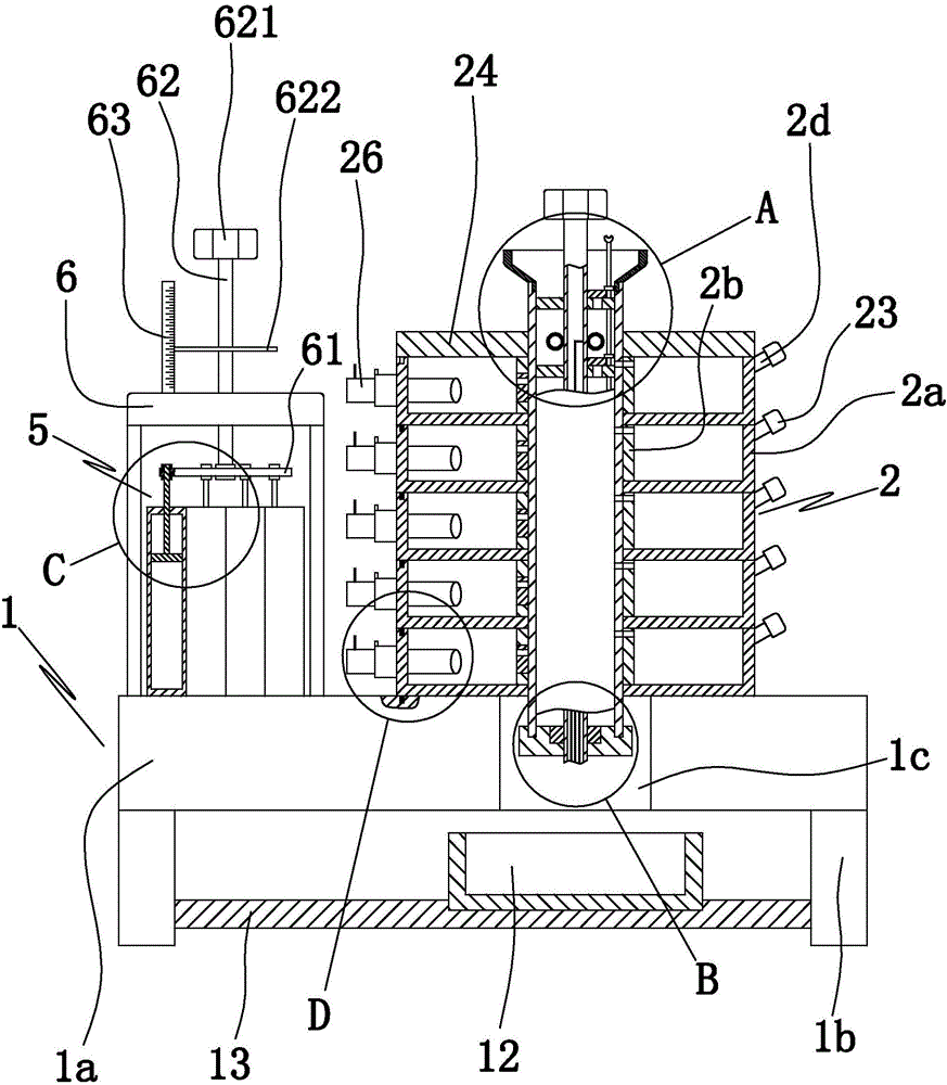
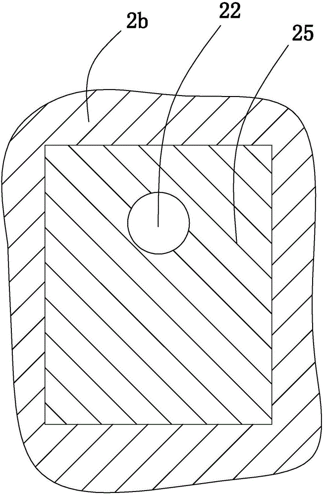
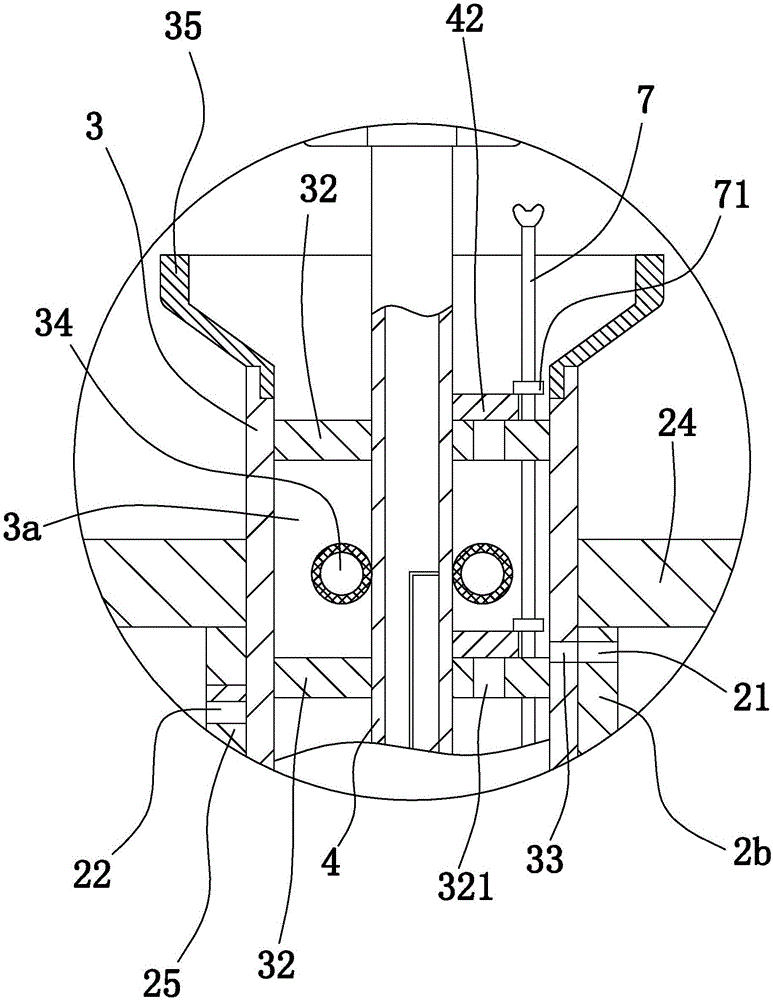
The invention discloses a culture carrier structure for a test. The culture carrier structure comprises a base and a plurality of culture dishes, wherein various culture dishes are stacked, the culture dish comprises a dish body, a vertical cylinder, a projecting block and a liquid injecting pipe, the end surface on the top portion of the dish body is provided with a dish top groove, the top portion of the base is provided with a base top groove, the projecting block on the bottom culture dish is positioned inside the base top groove, a rotation pipe penetrates through all vertical cylinders and can rotate relative to the vertical cylinders, the outer side wall of the rotation pipe and the inner side wall of the vertical cylinders form sealed contact, the outer side wall of the rotation pipe is provided with a liquid discharge groove, the vertical cylinder is provided with a liquid homogenizing hole communicated to the internal of the dish body, a cell filtration screen and a liquid homogenizing one-way valve are arranged inside the liquid homogenizing hole, the lower end of the liquid injecting pipe is communicated to the internal of the dish body, and the projecting block of the culture dish on the upper portion is positioned inside the dish top groove of the culture dish on the lower portion. According to the present invention, the culture carrier structure is suitable for cell culture and determination and comparison, and has beneficial effects of rational spatial arrangement, stable structure, convenient operation process, and good adjustment consistency and high accuracy during the test.

Description

technical field [0001] The invention belongs to the technical field of cell culture, in particular to a culture carrier structure for experiments. Background technique [0002] Cell culture is also called cell cloning technology, and the formal term in biology is cell culture technology. The growth of cells requires a nutrient environment, and the nutrient matrix used to maintain cell growth is called a medium. The medium can be divided into liquid medium and solid medium according to its physical state. In addition to being used in production, cell culture technology is currently used more in experiments (such as determining the parameters of group samples, and conducting comparisons and research), and liquid culture media is commonly used in experiments. In addition, cell culture requires the use of cell culture devices, such as petri dishes, incubators, etc. Cell culture in general environments can directly use petri dishes, and if some special environments (such as pow...

Claims


Application Information

Patent Timeline
IPC IPC(8): C12M3/06C12M1/22
CPCC12M23/10C12M23/38C12M23/42C12M23/48C12M29/00C12M29/04C12M33/04
Inventor 王铁苗
Owner 凤阳县一星农业发展有限公司
Why Eureka
Try Eureka