
Steel pipe column and steel beam end plate connecting joint adopting single-face connecting bolts

A technology for connecting nodes and connecting bolts, which is applied to buildings and building structures, etc., can solve the problems of complex structure of expansion bolts, difficult to guarantee connection strength, and complicated bolt hole production, and achieve the effect of simple structure, convenient fixing and high strength.

Inactive Publication Date: 2016-12-21
SHANDONG UNIV
View PDF7 Cites 3 Cited by
  • Summary
  • Abstract
  • Description
  • Claims
  • Application Information

AI Technical Summary

Problems solved by technology

However, the structure of the expansion bolt is complicated, and a large torque is required to screw the large expansion head into the casing during installation, and the use of the expansion bolt will inevitably cause a great squeeze on the surrounding structure, and even cause damage, affecting the safety of the structure
The hot-melt drilling bolt is a hole with an internal thread formed by hot-melt drilling, and the outer bolt is directly screwed in to complete the fastening installation. The strength of this connection bolt mainly depends on the pull-out strength of the bolt from the hole. The bolt hole The production is complex and requires high precision, but the connection strength is difficult to guarantee

Method used


Image

  • Steel pipe column and steel beam end plate connecting joint adopting single-face connecting bolts
  • Steel pipe column and steel beam end plate connecting joint adopting single-face connecting bolts
  • Steel pipe column and steel beam end plate connecting joint adopting single-face connecting bolts

Examples


Embodiment Construction

[0032] The present invention will be further described below in conjunction with the accompanying drawings and embodiments.

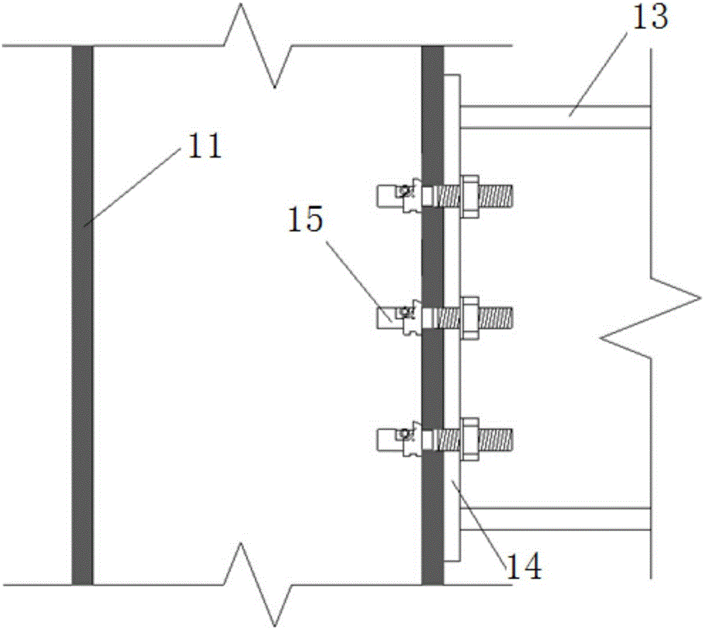
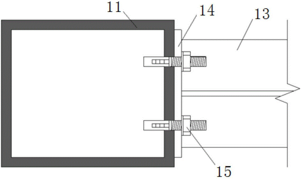
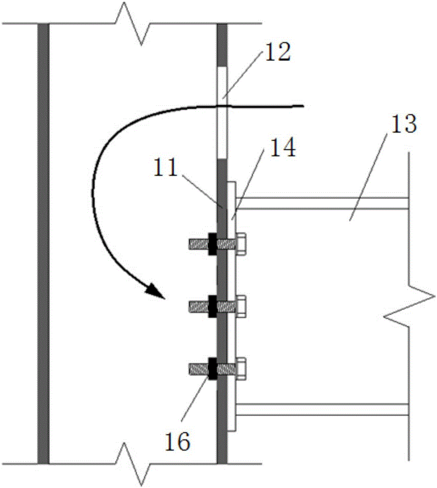
[0033] Such as Figure 1-Figure 2 As shown, a steel pipe column and steel beam end plate connection node using single-sided connection bolts includes: a rectangular steel pipe column 11 , an H-shaped steel beam 13 , an end plate 14 and a bolt 15 . Rectangular steel pipe columns 11 are provided with prefabricated bolt holes at the nodes of the column walls. H-shaped steel beams 13 are welded to end plates 14, and bolt holes are prefabricated on the end plates 14. The single-sided connection bolt 41 is inserted into the prefabricated bolt hole on the rectangular steel pipe column 11 and the end plate 14. After the construction site is installed in place, the bolt at the front end of the bolt bolt is unscrewed to form an anchor in the steel pipe column, and the nut is tightened from the outside to complete the single-sided connection. The assembly of edg...


PUM


Abstract

The invention discloses a steel pipe column and steel beam end plate connecting joint adopting single-face connecting bolts. The steel pipe column and steel beam end plate connecting joint comprises a steel pipe column and a steel beam, one end of the steel beam is fixedly connected with an end plate, and prefabricated bolt holes are formed in the positions, corresponding to the steel pipe column, of the end plate. The single-face connecting bolts penetrate into the prefabricated bolt holes in a fastened mode. Each single-face connecting bolt comprises a bolt column, wherein one end of the bolt column is provided with a thread, and a groove is formed in the other end of the bolt column. A limiting part is rotatably connected into each groove, one end of each limiting part is matched with a clamp-stopping part used for preventing the limiting part from rotating, and an ejecting part is connected between the other end of each limiting part and the corresponding bolt column. Before the limiting parts rotate, the clamp-stopping parts enable the limiting parts to be completely embedded into the grooves, the ejecting parts eject the limiting parts to enable the limiting parts to rotate after the clamp-stopping parts are loosened, and the limiting parts protrude out of the grooves. After in-place installation on site, the single-face connecting bolts are inserted into the prefabricated bolt holes, assembling of the joint can be completed by screwing nuts from the outer side, single-face connection is achieved, welding is not needed in a construction site, and the assembling degree is higher.

Description

technical field [0001] The invention belongs to the technical field of steel structure connection, in particular to a connection node between a steel pipe column and a steel beam end plate using single-sided connection bolts. Background technique [0002] The section of the steel pipe column is a closed section, and its connection with the steel beam is more complicated than that of the open section beam-column connection. It is necessary to open temporary hand holes on the steel pipe wall to install the internal nuts. After the bolts are installed, they need to be welded on site to close the temporary hand holes. Weld volume. In order to reduce the amount of welding on the construction site and increase the degree of assembly of the steel structure, single-sided connection bolts can be used in this type of connection to realize unilateral assembly connection nodes. [0003] Single-sided connecting bolts refer to fasteners that only need to be operated on one side of the c...

Claims


Application Information

Patent Timeline
IPC IPC(8): E04B1/24
CPCE04B1/24E04B1/2403E04B2001/2406E04B2001/2418
Inventor 王培军刘昌斌刘梅朱绪林
Owner SHANDONG UNIV
Learn More