Engine waste heat comprehensive recovery system

A recovery system and engine technology, applied in the direction of machines/engines, mechanical equipment, steam engine devices, etc., can solve problems such as energy waste, environmental pollution, etc., and achieve the effects of convenient operation, improved integrity, and easy control

Active Publication Date: 2016-12-21
HARBIN INST OF TECH AT WEIHAI
View PDF9 Cites 20 Cited by
  • Summary
  • Abstract
  • Description
  • Claims
  • Application Information

AI Technical Summary

Problems solved by technology

[0003] In order to solve the problems of excessive waste of energy and environmental pollution caused by the inability to fully utilize the waste heat of engine exhaust and cooling water, scientific and technological pers...

Method used


Image

  • Engine waste heat comprehensive recovery system
  • Engine waste heat comprehensive recovery system

Examples


Embodiment Construction

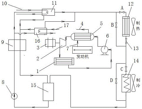
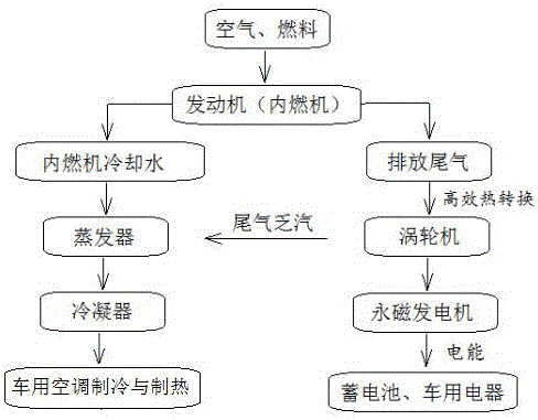
[0014]A comprehensive engine waste heat recovery system mainly includes an engine high-grade energy recovery system and a lithium bromide absorption cycle refrigeration (heat) system. The high-grade energy recovery system of the engine includes an engine exhaust exhaust pipe 7, a working medium pump 6, an evaporative heat exchanger 5, a single-screw expander 2, a generator 3, a condenser I (1) and an engine exhaust gas exhaust pipe 4. The evaporative heat exchanger 5 (essentially a shell-and-tube heat exchanger) is connected to the exhaust pipe 7 of the engine, and the outlet of the evaporative heat exchanger 5 is connected to the generator set, which is composed of a single-screw expander 2 and a power generation unit. The single-screw expander 2 is connected to the inlet of the condenser I (1), the outlet of the condenser I (1) is connected to the working fluid pump 6, and the working fluid pump 6 is connected to the inlet of the evaporating heat exchanger 5, wherein The wor...


PUM


Abstract

The invention relates to an engine waste heat comprehensive recovery system. The engine waste heat comprehensive recovery system comprises a condenser I, a single-screw expander, a power generator, an engine tail gas exhaust gas exhaust pipe, an evaporative heat exchanger, a working medium pump, an engine tail gas exhaust pipe, a solution pump, a solution heat exchanger, an engine connected cooling water pipe, a first generator, a condenser II, a throttle valve, an evaporator, an absorber, a second generator, an engine connected tail gas exhaust gas exhaust pipe and stop valves A, B, C and D. The engine waste heat comprehensive recovery system has the advantages that the engine high-grade energy recovery system is used for recovering tail gas with high-grade energy, treated tail gas exhaust gas and low-grade energy engine cooling water jointly serve as a heat source to drive a lithium bromide absorption refrigerator for full recovery of tail gas heat, designed valve group-condenser-evaporator units are used in the engine heat recovery system, the function integrity of the system is improved, and the purposes of convenient and rapid operation and easy control are achieved.

Description

technical field [0001] The invention relates to the field of waste heat recovery of automobile engines, in particular to an engine waste heat comprehensive recovery system. Background technique [0002] Since the 1990s, my country's national economy has developed rapidly, the automobile industry has developed rapidly, the number of automobiles has continued to increase, and the oil consumption has also increased sharply. With the increase in oil consumption, environmental problems have become increasingly prominent. According to relevant data records: 30% of the fuel oil of the automobile engine is converted into mechanical energy (as power), 40% is exhaust gas loss (partially converted by turbocharger), 20% is coolant and engine oil loss, and 10% is friction loss. Therefore, the actual efficiency of automobile engines is generally 35%-40%, and nearly 50% of the energy of automobile fuel is discharged through exhaust gas and cooling water, resulting in a large amount of ener...

Claims


Application Information

Patent Timeline
IPC IPC(8): F01K25/10F01K23/10B60H1/18
CPCB60H1/18F01K23/065F01K23/10F01K25/10
Inventor 崔文政毛东旭杨建国沈照杰吴少华
Owner HARBIN INST OF TECH AT WEIHAI
Why Eureka
Try Eureka