A liquid flow constant control device

A technology of constant control and liquid flow, which is applied in the direction of flow control of auxiliary non-electric power, valve device, valve housing structure, etc., and can solve problems such as change, spring elastic coefficient change, flow instability, etc.

Active Publication Date: 2018-09-14
JIANGSU YONGGUAN WATER & WASTERWATER EQUIP CO LTD
View PDF8 Cites 0 Cited by
  • Summary
  • Abstract
  • Description
  • Claims
  • Application Information

AI Technical Summary

Problems solved by technology

Although this automatic constant pressure and constant flow valve can realize that the cross section of the liquid flow channel changes inversely with the change of the liquid pressure, it realizes the control of the water flow through the change of the gap of the spring, so there are the following deficiencies: one is the spring steel Long-term immersion in water will inevitably lead to corrosion, resulting in changes in the elastic coefficient of the spring, so the gap of the spring will also change, resulting in unstable flow
The second is that the compression or stretching of the spring requires a longer stroke, that is, the distance between the spring seat and the piston is longer, so when the water flow enters the inner cavity of the spring from the water inlet, due to the transmission of pressure, the inner cavity of the spring will be The pressure of the water flow is gradually balanced with the water pressure of the water inlet. At this time, the spring will gradually return to the initial state from the compressed state, that is to say, the gap between the springs will become larger; therefore, the effect of adding the spring and the piston is only to make the pressure change tend to Easing, it can only play the role of slowing down the pressure shock, it is difficult to really control the constant flow

Method used


Image

  • A liquid flow constant control device
  • A liquid flow constant control device
  • A liquid flow constant control device

Examples


Embodiment 1

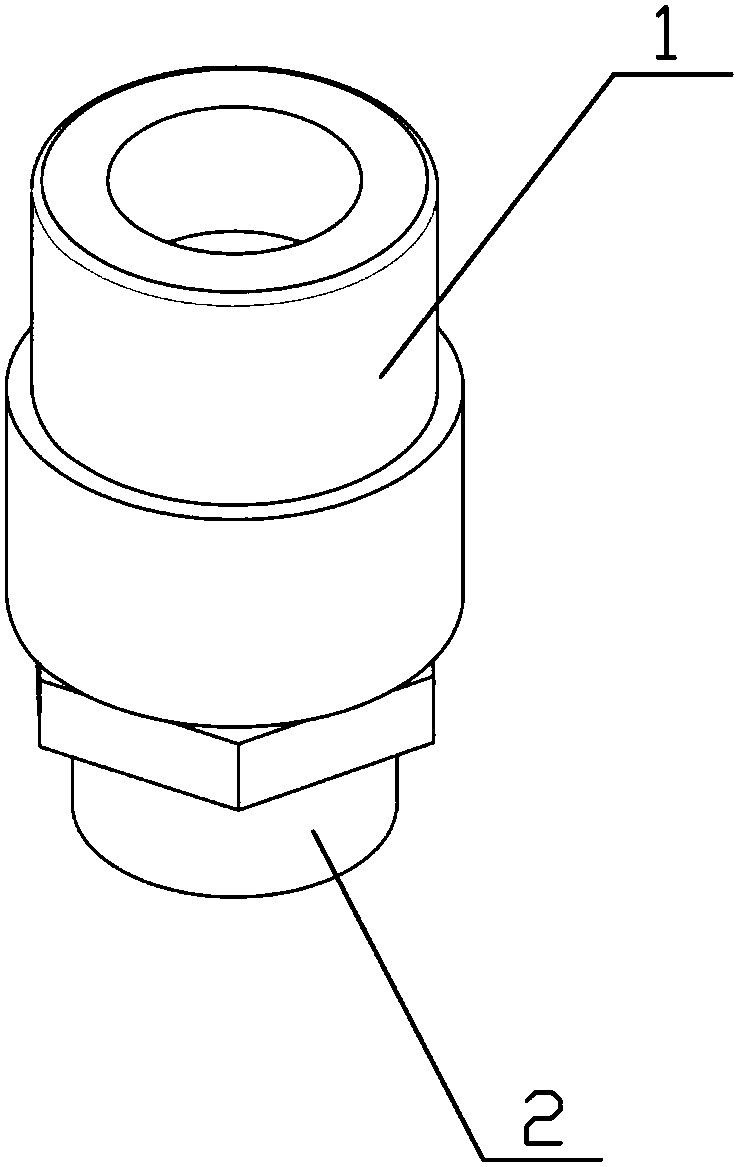
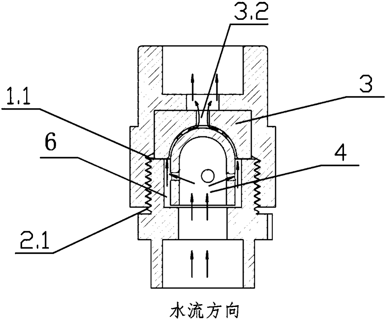
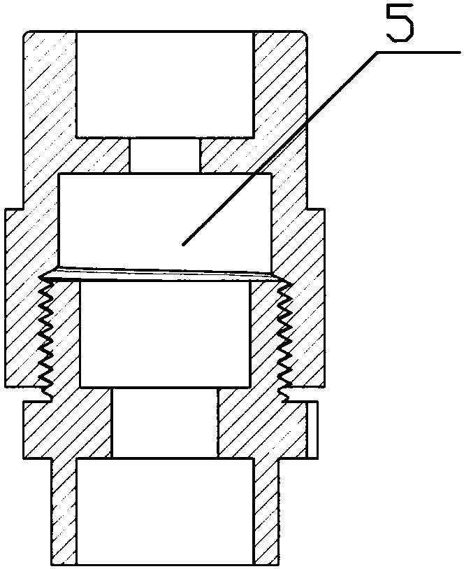
[0032] Example 1. refer to Figure 1-7 . A liquid flow constant control device of the present invention comprises an upper valve body (1), a lower valve body (2), an elastic pad (3) and a movable valve core (4), and the upper valve body (1) is provided with There are internal threads (1.1), and the lower valve body (2) is provided with external threads (2.1) matching with the upper valve body (1), and the upper valve body (1) and the lower valve body (2) are connected by internal and external threads And form the valve body cavity (5) after the upper valve body (1) and the lower valve body (2) are combined, in the valve body cavity (5), along the upper valve body (1) to the lower valve body (2 ) is provided with an elastic pad (3) with a hole and a movable valve core (4) in sequence in the axial direction, and the movable valve core (4) includes a semicircular sealing part (4.1) and a cylindrical The guide part (4.2), the outer surface of the semicircular sealing part (4.1)...

Embodiment 2

[0033]Example 2. refer to Figure 1-7 . A liquid flow constant control device of the present invention comprises an upper valve body (1), a lower valve body (2), an elastic pad (3) and a movable valve core (4), and the upper valve body (1) is provided with There are internal threads (1.1), and the lower valve body (2) is provided with external threads (2.1) matching with the upper valve body (1), and the upper valve body (1) and the lower valve body (2) are connected by internal and external threads And form the valve body cavity (5) after the upper valve body (1) and the lower valve body (2) are combined, in the valve body cavity (5), along the upper valve body (1) to the lower valve body (2 ) is provided with a holed elastic pad (3) and a movable spool (4) in sequence in the axial direction, and the movable spool (4) includes a semicircular sealing part (4.1) and a cylindrical The guide part (4.2), the outer surface of the semicircular sealing part (4.1) is provided with ...

Embodiment 3

[0034] Example 3. refer to Figure 1-7 . A liquid flow constant control device of the present invention comprises an upper valve body (1), a lower valve body (2), an elastic pad (3) and a movable valve core (4), and the upper valve body (1) is provided with There are internal threads (1.1), and the lower valve body (2) is provided with external threads (2.1) matching with the upper valve body (1), and the upper valve body (1) and the lower valve body (2) are connected by internal and external threads And form the valve body cavity (5) after the upper valve body (1) and the lower valve body (2) are combined, in the valve body cavity (5), along the upper valve body (1) to the lower valve body (2 ) is provided with a holed elastic pad (3) and a movable spool (4) in sequence in the axial direction, and the movable spool (4) includes a semicircular sealing part (4.1) and a cylindrical The guide part (4.2), the outer surface of the semicircular sealing part (4.1) is provided with...


PUM


Abstract

The invention relates to a constant control device for liquid flow. The constant control device for liquid flow is characterized in that the constant control device comprises an upper valve body, a lower valve body, an elastic cushion and a movable valve element; an internal thread is arranged on the upper valve body, and an external thread matched with the upper valve body is arranged on the lower valve body; the upper valve body and the lower valve body are connected through the internal thread and the external thread, and a valve body cavity is formed after the upper valve body and the lower valve body are combined; and in the valve body cavity, the elastic cushion with a hole, and the movable valve element are sequentially arranged in the axial direction from the upper valve body to the lower valve body, the movable valve element comprises a semicircular sealing part and a cylindrical guide part, protrusions are arranged on the outer surface of the semicircular sealing part, valve element through holes for circulation of liquid are formed in the circumferential wall of the cylindrical guide part, and the elastic cushion with the hole is provided with a seal surface attached to the semicircular sealing part. According to the constant control device for liquid flow, constant regulation of liquid flow can be achieved within a preset liquid pressure range without the influence of the change of the liquid pressure; and the constant control device is suitable for the fields of agricultural irrigation, solution proportioning, energy and water saving and the like.

Description

technical field [0001] The invention belongs to the technical field of liquid flow control valves, in particular to a constant liquid flow control device. Background technique [0002] Most of the existing water supply systems use water pumps to pressurize the water supply pipelines for water supply. In this case, with the start or stop of the water pumps, as well as the resistance of the pipeline itself and changes in water consumption, the pressure of the pipelines will change. ; or the water outlets at different positions where the pipeline is longer are due to the resistance of the pipeline, the water pressure at the end of the pipeline becomes smaller, and the water pressure near the front end of the pipeline is larger. Due to the above reasons, the flow rates of water outlet holes with the same diameter are quite different. In order to solve the problems existing in the existing water supply system, the known technical principle is to make the cross section of the liq...

Claims


Application Information

Patent Timeline
Patent Type & Authority Patents(China)
IPC IPC(8): F16K17/34F16K27/02F16K1/36
CPCF16K1/36F16K17/34F16K27/0245G05D7/03
Inventor 刘雨鞠茂森赵翠
Owner JIANGSU YONGGUAN WATER & WASTERWATER EQUIP CO LTD
Why Eureka
Try Eureka