Boiler slagging condition monitoring and controlling methods based on outlet temperature of combustion chamber

A furnace outlet and control method technology, applied in the direction of boiler working status indication, control system, lighting and heating equipment, etc., can solve the problems of shutdown installation, difficulty in power station boilers, and troublesome heat flow meter layout.

Active Publication Date: 2016-12-21
ZHEJIANG UNIV
View PDF3 Cites 11 Cited by
  • Summary
  • Abstract
  • Description
  • Claims
  • Application Information

AI Technical Summary

Problems solved by technology

The main disadvantages are: 1) The layout of the heat flow meter is cumbersome and needs to be welded on the water-cooled wall, which changes the structure of the water-cooled wall and reduces the strength of the water-cooled wall; 2) It is very difficult for the power plant boilers that have been put into operation , it is necessary to stop the furnace for installation, and it is also difficult to maintain the measuring points; 3) The price of the heat flow meter is generally more expensive, and it is difficul

Method used


Image

  • Boiler slagging condition monitoring and controlling methods based on outlet temperature of combustion chamber
  • Boiler slagging condition monitoring and controlling methods based on outlet temperature of combustion chamber
  • Boiler slagging condition monitoring and controlling methods based on outlet temperature of combustion chamber

Examples


Embodiment Construction

[0054] In order to make the technical means, creative features, workflow, and usage methods of the present invention easy to understand, the present invention will be further described below in conjunction with specific embodiments.

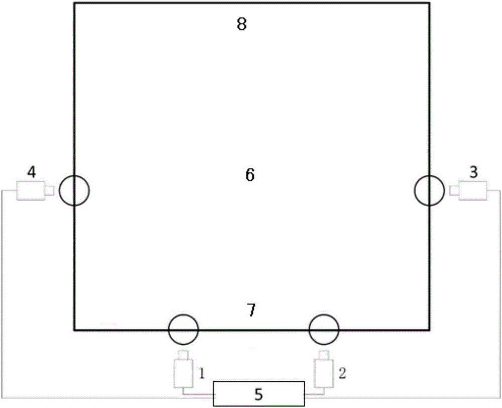
[0055] figure 1 It is a schematic diagram of the installation of the furnace outlet temperature matrix measurement method in this embodiment, including CCD1, CCD2, CCD3, CCD4 and a portable computer 5. The upper part of the furnace 6 is the rear wall 8, and the lower part is the front wall 7. Each CCD is installed on the furnace 6 to record the flame radiation image at each fire viewing hole. The image is segmented and extracted by computer, and the temperature is calculated to obtain the furnace outlet temperature. Matrix and the temperature change rate of the corresponding measuring points of each CCD, and then predict the commissioning time of the soot blower, reflecting the cleanliness of the water wall and the slagging characteristics of the...


PUM


Abstract

The invention discloses a boiler slagging condition monitoring method based on the outlet temperature of a combustion chamber. The monitoring method includes the steps of 1, detecting the outlet temperature of the combustion chamber; 2, calculating the temperature change before and after soot blowing and the temperature rising rate after soot blowing of an outlet of the combustion chamber according to detection in the step 1; and 3, judging that combusted coal tends to form slag when the temperature change is greater than 50 DEG C and the temperature rising rate is greater than 5 DEG/h, and judging that the combusted coal is not suitable for long-term combustion and adjusting the coal type when the temperature change is greater than 80 DEG C and the temperature rising rate is greater than 10 DEG/h. The invention further provides a boiler slagging condition controlling method based on the outlet temperature of the combustion chamber. According to the monitoring method and the controlling method, scientific use of a soot blower can be effectively guided, the outlet temperature of the combustion chamber can be continuously recorded, the temperature change before and after soot blowing and the temperature rising rate after soot blowing of the combustion chamber can be calculated, the use time of the soot blower can be further obtained, and the cleanliness degree of a water-cooled wall and the slagging characteristics of the coal type can be reflected.

Description

technical field [0001] The invention relates to the technical field of boiler combustion, in particular to a method for monitoring and controlling boiler slagging conditions based on furnace outlet temperature. Background technique [0002] When the boiler burns solid or liquid fuel containing ash, the heating surface of each part of the boiler is accompanied by mineral deposits to varying degrees. When the flue gas temperature is high, softened or molten ash particles stick to the heating surface during the combustion process, continue to grow and accumulate, resulting in slagging, resulting in deterioration of heat transfer, corrosion of the heating surface, and affecting the safe operation of the equipment. Boiler slagging is a very complicated process involving many factors. It is not only related to the composition and physical and chemical characteristics of the coal used, but also related to the design parameters of the boiler (such as the arrangement of the burner, t...

Claims


Application Information

Patent Timeline
IPC IPC(8): F22B37/38F22B35/00
CPCF22B35/00F22B37/38
Inventor 周永刚薛志亮李培施子福王肖周永青
Owner ZHEJIANG UNIV
Why Eureka
Try Eureka