Circulating heat dissipation pipe of air conditioner

A technology of air conditioning cycle and heat dissipation pipe, which is applied in the direction of tubular elements, heat transfer modification, indirect heat exchanger, etc. area, improve the cooling effect and increase the service life

Inactive Publication Date: 2016-12-21
ANHUI TIANXIANG AIR CONDITIONING SCI & TECH CO LTD
View PDF5 Cites 3 Cited by
  • Summary
  • Abstract
  • Description
  • Claims
  • Application Information

AI Technical Summary

Problems solved by technology

During this process, the heat dissipation efficiency of the air conditioner’s heat dissipation pipe plays a decisive role in the cooling effect of the air conditioner. If the heat dissipation pipe cannot quickly take away the heat in the refrigerant, it will increase the load on the compressor and increase the power consumption at the same time. The cooling effect is also poor
[0003] Existing air conditioners mainly rely on the mutual cooperation of heat sinks and heat sinks to dissipate heat through heat conduction. The effect is not ideal. The length of heat pipes is high, and the distribution density of heat sinks is also relatively large. The production materials are expensive, which increases the production cost of the enterprise

Method used


Image

  • Circulating heat dissipation pipe of air conditioner
  • Circulating heat dissipation pipe of air conditioner
  • Circulating heat dissipation pipe of air conditioner

Examples


Embodiment Construction

[0015] The following will clearly and completely describe the technical solutions in the embodiments of the present invention with reference to the accompanying drawings in the embodiments of the present invention. Obviously, the described embodiments are only some, not all, embodiments of the present invention. Based on the embodiments of the present invention, all other embodiments obtained by persons of ordinary skill in the art without making creative efforts belong to the protection scope of the present invention.

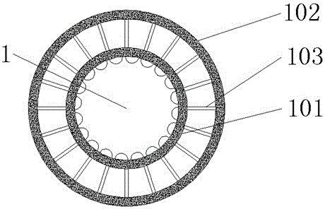
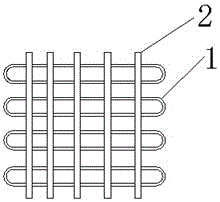
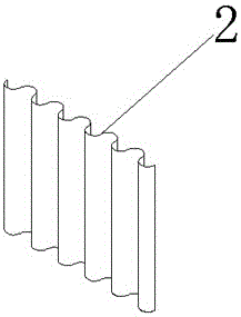
[0016] The present invention provides such Figure 1-3 The air-conditioning circulation heat pipe shown in the figure includes a heat pipe body 1 and a heat sink 2. The heat pipe body 1 runs through and is uniformly coiled inside the body of the heat sink 2. The heat pipe body 1 includes an inner pipe 101 and a heat sink 2. The outer cladding tube 102, the inner tube 101 is located at the center of the inner cavity of the outer cladding tube 102, and the oute...


PUM


Abstract

The invention discloses a circulating heat dissipation pipe of an air conditioner. The circulating heat dissipation pipe of the air conditioner comprises a heat dissipation pipe body and cooling fins. The heat dissipation pipe body transversely penetrates through the cooling fins and is evenly coiled inside bodies of the cooling fins. The heat dissipation pipe body comprises an inner pipe and an outer wrapper pipe, and the inner pipe is located in the center of an inner cavity of the outer wrapper pipe. Heat conduction sheets are perpendicularly arranged on the arc face of the outer side wall of the inner pipe, and the other end of each heat conduction sheet is perpendicularly and fixedly connected with the inner side wall of the outer wrapper pipe. The circulating heat dissipation pipe of the air conditioner adopts a dual-layer pipe compound structure, the cavity formed between the inner pipe and the outer wrapper pipe is filled with anti-freezing cooling liquid, refrigerating fluid flowing in the inner pipe is physically cooled through the cooling effect of the anti-freezing cooling liquid, the heat dissipation efficiency of the heat dissipation pipe is greatly improved, the refrigeration effect of the air conditioner is improved, and electricity energy is saved. In the production process, the arraying density of the cooling fins and the length of the heat dissipation pipe body can be reduced, the production cost is reduced for enterprises, and the circulating heat dissipation pipe of the air conditioner is worthy of popularization.

Description

technical field [0001] The invention belongs to the technical field of air-conditioning heat dissipation, and in particular relates to an air-conditioning circulation heat dissipation pipe. Background technique [0002] When the air conditioner is cooling in summer, the low-pressure steam of the refrigerant in the refrigeration system is sucked by the compressor and compressed into high-pressure steam and then discharged to the condenser. At the same time, the outdoor air sucked by the axial fan flows through the condenser to take away the heat released by the refrigerant. Condensing high-pressure refrigerant vapor into high-pressure liquid. The high-pressure liquid is sprayed into the evaporator after passing through the filter and throttling mechanism, and evaporates at the corresponding low pressure to absorb the surrounding heat. The cooled air is sent to the room. In this way, the indoor air is continuously circulated to achieve the purpose of cooling and lowering the...

Claims


Application Information

Patent Timeline
Patent Type & Authority Applications(China)
IPC IPC(8): F28D1/047F28F1/10F28F13/18F25B39/00
CPCF28D1/047F25B39/00F28F1/10F28F13/182
Inventor 骆宣佐
Owner ANHUI TIANXIANG AIR CONDITIONING SCI & TECH CO LTD
Why Eureka
Try Eureka