
Vibration amplifier and testing method for simulating high-order nonlinear vibration fatigue of blade

A test method and amplifier technology, applied in the field of material fatigue fracture and high cycle fatigue test, can solve the problems of nonlinear stiffness, unsolved resonance, and small frequency adjustment range.

Active Publication Date: 2016-12-21
中国人民解放军空军工程大学航空航天工程学院
View PDF10 Cites 23 Cited by
  • Summary
  • Abstract
  • Description
  • Claims
  • Application Information

AI Technical Summary

Problems solved by technology

[0004] In the design of high-order vibration fatigue test method, there are mainly problems of excitation difficulty: on the one hand, because the excitation requires a larger vibration acceleration, on the other hand, because the reaction force on the vibration table during resonance will reduce the vibration of the vibration table. output vibration acceleration
The existing technology proposes to set up a fixture support body, protruding symmetrical shafts on both sides of the support body, and generate high acceleration through the resonance of the shaft body, but it does not solve the problem of suppressing vibration caused by the reaction force caused by resonance
In addition, the shaft in this patent is fixed, and the resonant frequency is adjusted by moving the specimen fixture. This method has a small frequency adjustment range, and the cross-section of the shaft is circular, which is prone to torsional vibration. At the same time, the shaft and the fixture Fixed connection is prone to torsion
[0005] In the process of high-order vibration fatigue experiments, due to factors such as material properties and mode shape geometric properties, stiffness nonlinear phenomena will be caused, resulting in changes in its natural frequency, making it difficult for the vibration control system to track the resonance peak

Method used


Image

  • Vibration amplifier and testing method for simulating high-order nonlinear vibration fatigue of blade
  • Vibration amplifier and testing method for simulating high-order nonlinear vibration fatigue of blade
  • Vibration amplifier and testing method for simulating high-order nonlinear vibration fatigue of blade

Examples


Embodiment Construction

[0037] The present invention is described in further detail below in conjunction with accompanying drawing:

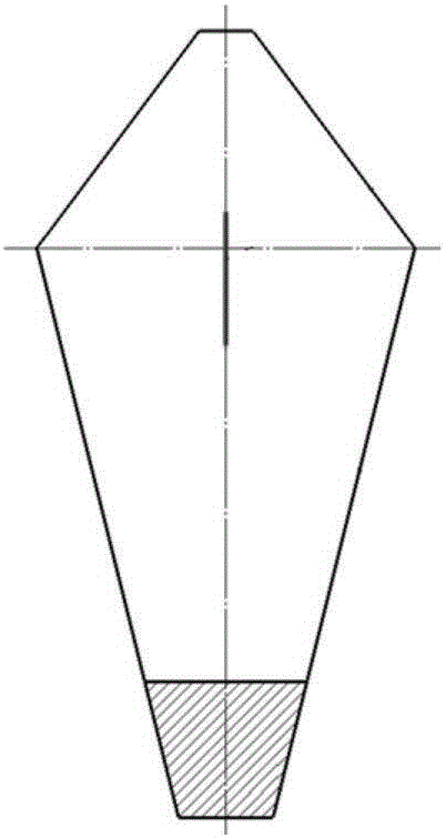
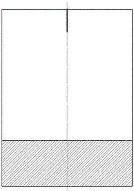
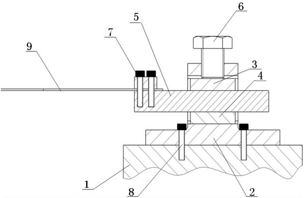
[0038]The vibration amplifier of the present invention includes a base 2, a fixed housing, an upper pad 3, a lower pad 4, a first fixing screw 7, a second fixing screw 6, an amplifying arm 5 and a clamping block 10; an upper pad 3 and the lower pad 4 are located in the fixed housing, and one end of the amplifying arm 5 passes through one side of the fixed housing, between the upper pad 3 and the lower pad 4, and the other side of the fixed housing to extend out to the fixed housing. Outside the housing, the clamping block 10 is located on the upper surface of the other end of the amplifying arm 5, and the first fixing screw 7 passes through the clamping block 10 and the amplifying arm 5 to connect the clamping block 10 with the amplifying arm 5, and the second fixing screw 6 Pass through the top of the fixed housing and extend into the fixed housing to contact the uppe...


PUM


Abstract

The invention discloses a vibration amplifier and a testing method for simulating the high-order nonlinear vibration fatigue of a blade. The vibration amplifier comprises a base, a fixed shell, an upper cushion block, a lower cushion block, first fixing screws, a second fixing screw, an amplification arm and a clamping block; the upper cushion block and the lower cushion block are located in the fixed shell; one end of the amplification arm sequentially passes through one side surface of the fixed shell, a space between the upper cushion block and the lower cushion block, and the other side surface of the fixed shell, and then extends out from the fixed shell; the clamping block is located on the upper surface of the other end of the amplification arm; the first fixing screws pass through the clamping block and the amplification arm, so that the clamping block can be connected with the amplification arm; and the second fixing screw passes through the top of the fixed shell, extends into the fixed shell and contacts with the upper surface of the upper cushion block, so that the upper cushion block, the lower cushion block and the amplification arm can be fixedly connected with one another. With the amplifier and the method adopted, detection on the fatigue strength of the blade can be realized based on a fatigue testing process of resonance frequency and amplitude.

Description

technical field [0001] The invention belongs to the field of material fatigue fracture and high-cycle fatigue test methods, and relates to a vibration amplifier and a test method for simulating high-order nonlinear vibration fatigue of blades. Background technique [0002] Aeroengines, ground gas turbines and other high-speed rotating machinery have variable working conditions and are always under a complex and harsh working condition. High-cycle fatigue fracture of rotor blades is the most common and serious failure problem, and vibration fatigue is the main fatigue form. . [0003] At present, the fatigue performance assessment method of blades still mainly adopts the first-order bending vibration fatigue test, and the main assessment is the fatigue performance of the blade root (one-pitch line). have been effectively avoided. However, fatigue failures such as blade drop-off and cracks caused by high-order vibrations are still very serious, especially after the blades ar...

Claims


Application Information

Patent Timeline
Patent Type & Authority Applications(China)
IPC IPC(8): G01M7/02
CPCG01M7/022
Inventor 何卫锋刘景元程礼聂祥樊周留成李媛李思路罗思海游熙
Owner 中国人民解放军空军工程大学航空航天工程学院
Learn More