Impedance matching unit, system and method used for calibrating high-frequency current sensor

A technology of impedance matching and high-frequency current, which is applied in the direction of instruments, measuring electrical variables, measuring devices, etc., can solve the problems of impedance matching and insufficient bandwidth, distortion, and the inability to truly reflect the broadband characteristics of high-frequency current sensors, so as to improve the broadband characteristics Effect

Active Publication Date: 2016-12-21
STATE GRID BEIJING ELECTRIC POWER +3
View PDF5 Cites 7 Cited by
  • Summary
  • Abstract
  • Description
  • Claims
  • Application Information

AI Technical Summary

Problems solved by technology

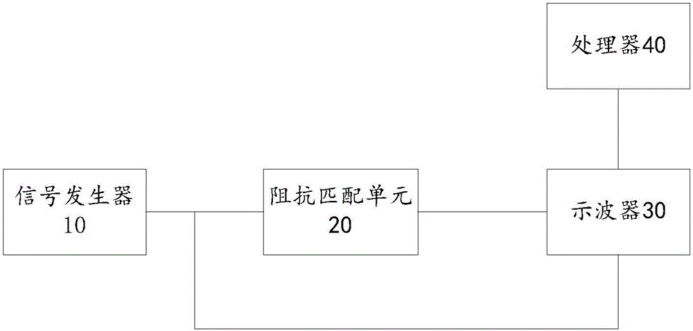
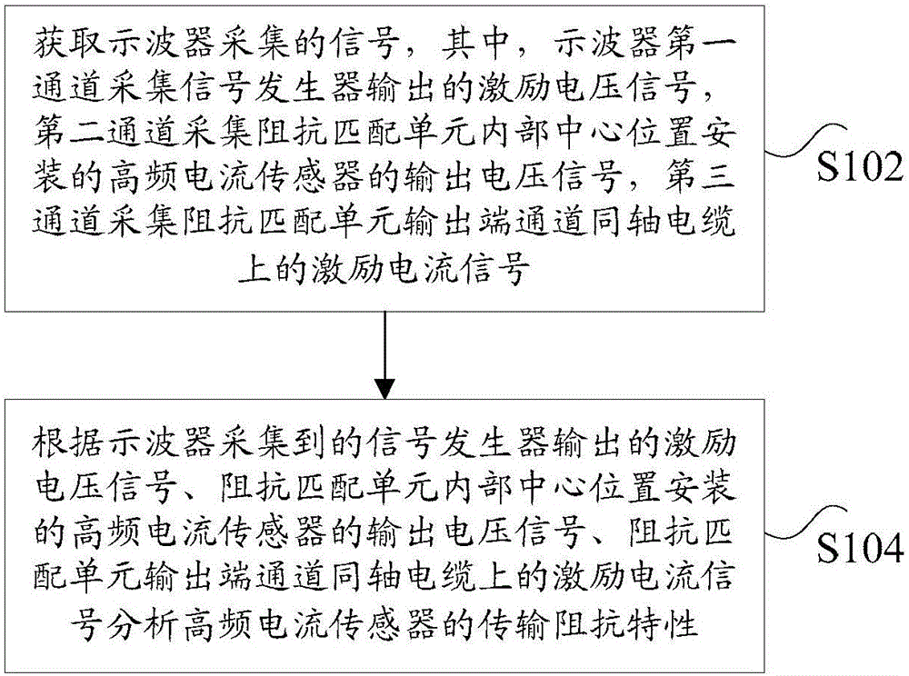
[0005] Embodiments of the present invention provide an impedance matching unit, system and method for calibrating high-frequency current sensors, so as to at least solve the problem of calibration results in the high-frequency range of the high-frequency current sensor pe

Method used


Image

  • Impedance matching unit, system and method used for calibrating high-frequency current sensor
  • Impedance matching unit, system and method used for calibrating high-frequency current sensor
  • Impedance matching unit, system and method used for calibrating high-frequency current sensor

Examples


Example Embodiment

[0021] In order to enable those skilled in the art to better understand the solutions of the present invention, the technical solutions in the embodiments of the present invention will be described clearly and completely with reference to the accompanying drawings in the embodiments of the present invention. Obviously, the described embodiments are only It is a part of the embodiments of the present invention, not all the embodiments. Based on the embodiments of the present invention, all other embodiments obtained by those of ordinary skill in the art without creative work shall fall within the protection scope of the present invention.

[0022] It should be noted that the terms "first" and "second" in the specification and claims of the present invention and the above-mentioned drawings are used to distinguish similar objects, and not necessarily used to describe a specific sequence or sequence. It should be understood that the data used in this way can be interchanged under ap...


PUM


Abstract

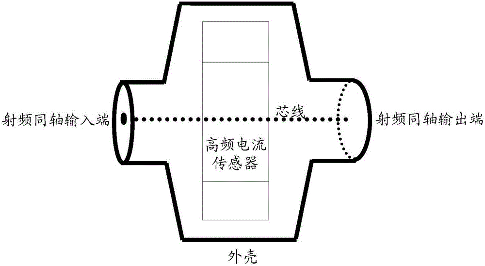
The invention discloses an impedance matching unit, a system and a method used for calibrating a high-frequency current sensor. The impedance matching unit is a transmission line structure formed by a radio frequency coaxial line with the characteristic impedance being 50ohm. The high-frequency current sensor is installed at a central position inside the impedance matching unit. The transmission line structure comprises a radio frequency coaxial input end, a radio frequency coaxial output end and a shell, wherein a core wire inside the transmission line structure penetrates through the radio frequency coaxial input end and the radio frequency coaxial output end; and the shell transits towards the middle from the radio frequency coaxial input end and the radio frequency coaxial output end so as to form a conical transition structure. The impedance matching unit disclosed by the invention solves a technical problem in relevant technologies that broadband characteristics of the high-frequency current sensor cannot be authentically reflected due to a calibration result of a high-frequency current sensor performance detection method in a high frequency interval has great distortion because of deficient impedance matching and bandwidth and the like.

Description

technical field [0001] The invention relates to the field of power electronics, in particular to an impedance matching unit, system and method for calibrating a high-frequency current sensor. Background technique [0002] Partial discharge is a non-penetrating discharge phenomenon caused by local defects in the insulating medium. Local defects (such as bubbles, cracks, suspended metal particles and electrode burrs, etc.) Partial discharge faults occur under certain operating conditions. Partial discharge is an important symptom of insulation cracking in the long-term operation of electrical equipment such as transformers and cables. Partial discharge failures in equipment can eventually lead to catastrophic failure of electrical equipment if they remain undetected and untreated. Partial discharge detection can effectively reflect the internal insulation faults of high-voltage electrical equipment, especially for the early detection of sudden faults, which is much more effe...

Claims


Application Information

Patent Timeline
IPC IPC(8): G01R35/00
CPCG01R35/005
Inventor 任志刚李伟唐志国毕建刚段大鹏桂媛徐兴全石磊张玉佳赵雪骞李邦彦
Owner STATE GRID BEIJING ELECTRIC POWER
Why Eureka
Try Eureka