Microstrip antenna unit and microstrip antenna

A technology of microstrip antenna and bandwidth, applied in the direction of antenna, antenna array, antenna grounding device, etc., can solve the problems of increased design difficulty, difficult scanning blind spots, suppression, etc., to achieve enhanced broadband characteristics, easy processing and implementation, and improve radiation efficiency Effect

Active Publication Date: 2018-12-28
LEIHUA ELECTRONICS TECH RES INST AVIATION IND OF CHINA
View PDF8 Cites 4 Cited by
  • Summary
  • Abstract
  • Description
  • Claims
  • Application Information

AI Technical Summary

Problems solved by technology

[0005] In order to solve the problems mentioned in the above-mentioned background technology, that is, in order to solve the problem that the existing blind spot suppression technology is difficult to suppress the scanning blind spot in a wide frequency range and the need to introduce additional structures leads to increased design difficulty, the present invention provides a A microstrip antenna unit, the microstrip antenna unit includes a dielectric plate and a first feed structure, a

Method used


Image

  • Microstrip antenna unit and microstrip antenna
  • Microstrip antenna unit and microstrip antenna
  • Microstrip antenna unit and microstrip antenna

Examples


Example Embodiment

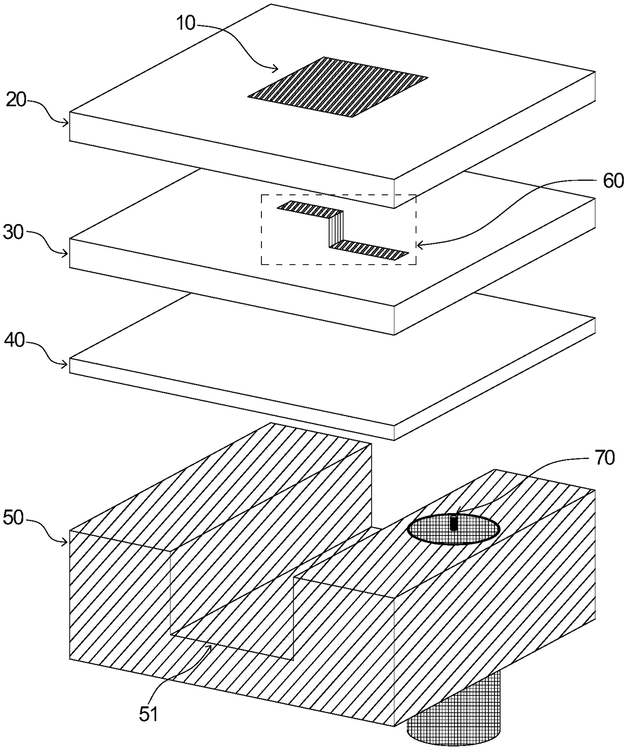
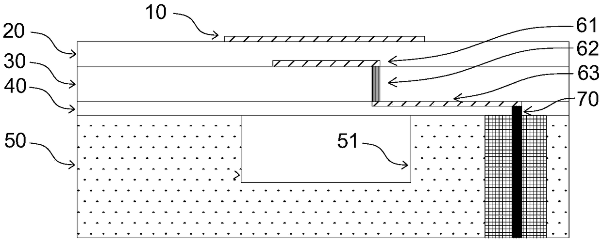
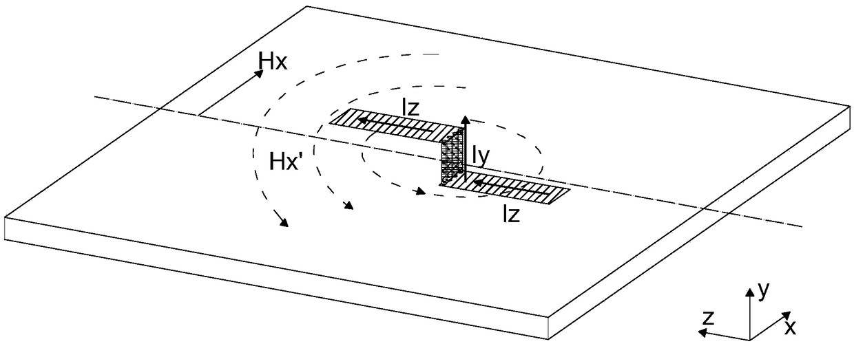
[0023] In order to make the objectives, technical solutions, and advantages of the implementation of the present invention clearer, the technical solutions in the embodiments of the present invention will be described in more detail below in conjunction with the accompanying drawings in the embodiments of the present invention. In the drawings, the same or similar reference numerals indicate the same or similar elements or elements with the same or similar functions. The described embodiments are part of the embodiments of the present invention, rather than all of the embodiments. The embodiments described below with reference to the accompanying drawings are exemplary, and are intended to explain the present invention, but should not be construed as limiting the present invention. Based on the embodiments of the present invention, all other embodiments obtained by those of ordinary skill in the art without creative work shall fall within the protection scope of the present inv...


PUM


Abstract

The invention belongs to the technical field of active phased array radar and antennas. In order to solve the problems that the existing blind spot suppression techniques cannot suppress the scanningblind spots in a wide frequency range and the design difficulty increases due to the introduction of additional structures, the present invention provides a microstrip antenna unit comprising a dielectric plate and a feeding structure arranged on the dielectric plate, the feeding structure being used for suppressing scanning blind spots of the microstrip antenna array. By vertically arranging thesecond feeding structure in the dielectric plate, the surface wave of the microstrip antenna element can be effectively suppressed, thereby eliminating the scanning blind spots of the microstrip antenna array in a wide scanning range.

Description

technical field [0001] The invention belongs to the field of active phased array radar and antenna technology, and in particular relates to a microstrip antenna unit and a microstrip antenna. Background technique [0002] In active phased array radar, the antenna array is used to receive and transmit radio frequency signals. Through the control of amplitude and phase, while forming a specified beam, it can also scan the beam in space. Microstrip patch antennas have the advantages of low profile, light weight, simple structure, and easy design and processing. However, traditional microstrip antennas have narrow bandwidth and low radiation efficiency, which cannot meet the requirements of phased array systems for wide operating frequency bands. At the same time, the realization of functions such as active phased array fast beam agility and large-angle electronic scanning requires the antenna unit to have wide-angle scanning characteristics. However, since the microstrip anten...

Claims


Application Information

Patent Timeline
IPC IPC(8): H01Q1/36H01Q1/48H01Q1/50H01Q21/06
CPCH01Q1/36H01Q1/48H01Q1/50H01Q21/065
Inventor 王琳月陈敏吴杨生
Owner LEIHUA ELECTRONICS TECH RES INST AVIATION IND OF CHINA
Why Eureka
Try Eureka