Distributed energy remote monitoring management system and method

A distributed energy and remote monitoring technology, applied in the field of distributed energy remote monitoring and management systems, can solve problems such as the inability of real-time data and performance comparison of distributed energy resources, the troublesome unified management of equipment, and the different power generation efficiency and combustion indicators. Improve overall efficiency and economic benefits, enhance safety and reliability, and improve work efficiency

Inactive Publication Date: 2016-12-21
HUADIAN ELECTRIC POWER SCI INST CO LTD
View PDF7 Cites 9 Cited by
  • Summary
  • Abstract
  • Description
  • Claims
  • Application Information

AI Technical Summary

Problems solved by technology

The host equipment has various types of units, most of which are imported with original packaging, and the power generation efficiency and combustion indicators are different, so the unified management of equipment is troublesome
[0005] (3) Since the installed capacity of distributed energy is based on project requirements, the planning of each distributed energy is different, resulting in the inability to compare data and performance of different distributed energy in real time
[0006] Although there are also some distributed energy management technologies, such as the Chinese patent whose publication date is December 14, 2011 and whose publication number is CN102280937A, a distributed energy monitoring system and method are disclosed; another example is that the publication date is 2014 On November 26, 2019, the Chinese patent with the publication number CN203968150U disclosed a distributed energy remote intensive management system, but these technologies are difficult to effectively solve the above problems

Method used


Image

  • Distributed energy remote monitoring management system and method

Examples


Embodiment Construction

[0025] The present invention will be further described in detail below in conjunction with the accompanying drawings and examples. The following examples are explanations of the present invention and the present invention is not limited to the following examples.

[0026] Example.

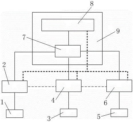
[0027] see figure 1 , the distributed energy remote monitoring and management system in this embodiment includes a gas distributed data on-site acquisition module 1, a gas distributed data protocol conversion module 2, a distributed photovoltaic data on-site acquisition module 3, and a distributed photovoltaic data protocol conversion module 4. Load data local collection module 5, load data protocol conversion module 6 and distributed energy processing center 9, wherein distributed energy processing center 9 includes central manager 7 and distributed energy remote analysis system module 8.

[0028] In this embodiment, the central manager 7 is connected to the distributed energy remote analysis sys...


PUM


Abstract

The invention relates to a distributed energy remote monitoring management system and method, for solving the problem of application inconvenience of a conventional distributed energy remote monitoring management system. The system is characterized by comprising a combustion gas distributed data onsite acquisition module, a combustion gas distributed data protocol conversion module, a distributed photovoltaic data onsite acquisition module, a distributed photovoltaic data protocol conversion module, a load data onsite acquisition module, a load data protocol conversion module and a distributed energy processing center, wherein the distributed energy processing center comprises a central processor and a distributed energy remote analysis system module, the combustion gas distributed data onsite acquisition module is connected with the combustion gas distributed data protocol conversion module, the distributed photovoltaic data onsite acquisition module is connected with the distributed photovoltaic data protocol conversion module, and the load data onsite acquisition module is connected with the load data protocol conversion module. According to the invention, the total operation state of each region and distributed energy station equipment can be grasped in real time.

Description

technical field [0001] The invention relates to a distributed energy remote monitoring management system and method. Background technique [0002] In the context of the country's vigorous development of distributed energy, distributed energy has shown a trend of rapid development in recent years. However, due to the late start of research on key technologies of distributed energy in my country and the dependence on foreign countries for the design and manufacturing technology of the whole machine, it has brought a lot to the rapid development. The problem is manifested in the following aspects. [0003] (1) The project is small in scale and scattered in layout. Compared with traditional thermal power and hydropower projects, the installed capacity of distributed energy is small and the layout points are scattered, which brings inconvenience to the centralized management and operation of distributed energy stations. [0004] (2) There are many distributed host manufacturers ...

Claims


Application Information

Patent Timeline
Patent Type & Authority Applications(China)
IPC IPC(8): G05B19/418H02J13/00
CPCG05B19/4185H02J13/0006Y02B90/20Y02P90/02Y04S20/00
Inventor 周宇昊张钟平刘丽丽宋胜男徐荻森张志勇阮慧锋王勇
Owner HUADIAN ELECTRIC POWER SCI INST CO LTD
Why Eureka
Try Eureka