Sub-pixel image synthesis method of dual line array imaging device based on multi-resolution analysis
An imaging device and image synthesis technology, applied in the field of space remote sensing imaging, can solve the problems of complex image restoration process, limited image resolution, and no effective analysis of the entire image.
- Summary
- Abstract
- Description
- Claims
- Application Information
AI Technical Summary
Problems solved by technology
Method used
Image


Examples
Embodiment 1
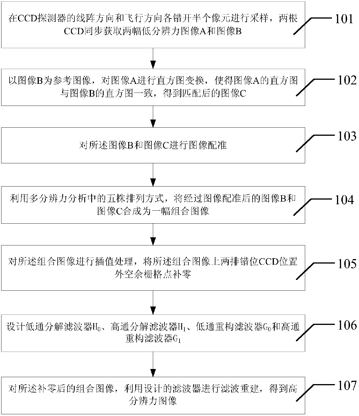
[0096] see figure 1 Shown is a flow chart of a sub-pixel image synthesis method of a dual linear array imaging device based on multi-resolution analysis described in this application, the sub-pixel image synthesis method of a dual linear array imaging device based on multi-resolution analysis includes:
[0097] Step 101, in the imaging detector represented by the linear array CCD, package the two linear array CCDs in the same focal plane device, or simultaneously image the two linear arrays by means of optical splitting, and combine the two linear array CCDs Stagger half a pixel in the line array direction and flight direction respectively, and acquire two low-resolution images A and B respectively;
[0098] Step 102: Using the image B as a reference image, perform a histogram transformation on the image A, so that the histogram of the image A is consistent with the histogram of the image B Figure 1 Consistent, get the matched image C;
[0099] Step 103, performing image re...
Embodiment 2
[0107] On the basis of the method described in Embodiment 1, in the above step 101, the two linear array CCDs are respectively staggered by half a pixel in the linear array direction and the flight direction, and two low-resolution images A and image B are obtained respectively, further as follows:
[0108] Using prism spectroscopic technology, sampling is carried out by staggering half a pixel in the linear array direction and flight direction of the CCD detector, see figure 2 , according to the linear array direction and the flight direction, the CCD detector (shown as CCD in the figure A and CCD B ) center coordinates are set to (0,0) and (0,p / 2) respectively. During the push-broom imaging process, two CCDs acquire two low-resolution images A and B at the same time.
[0109] In the above step 102, the process of histogram matching can be found in image 3 , through the detector CCD A Image A is acquired through the detector CCD B Image B is obtained, and image B is use...
PUM
 Abstract
Description
Claims
Application Information