Electric load decomposition method and system

A technology of electric load and decomposition coefficient, which is applied in the field of electric power and can solve the problems of low accuracy of electric load decomposition

Active Publication Date: 2019-01-15
ELECTRIC POWER RESEARCH INSTITUTE, CHINA SOUTHERN POWER GRID CO LTD
View PDF3 Cites 0 Cited by
  • Summary
  • Abstract
  • Description
  • Claims
  • Application Information

AI Technical Summary

Problems solved by technology

However, the traditional non-intrusive power load decomposition scheme only considers the active power of electrical equipment, and the accuracy of power load decomposition is low

Method used


Image

  • Electric load decomposition method and system
  • Electric load decomposition method and system
  • Electric load decomposition method and system

Examples


Embodiment 1

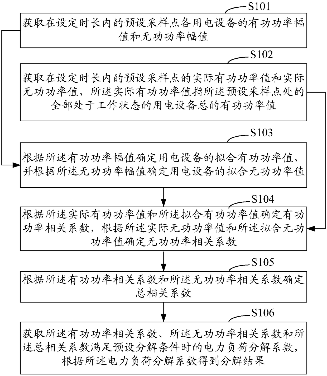
[0029] Embodiment 1 of the present invention provides a power load decomposition method, see figure 1 As shown in FIG. 1 , it is a schematic flow chart of the implementation of the power load decomposition method in Embodiment 1 of the present invention. Such as figure 1 As shown, the power load decomposition method of this embodiment includes the following steps:

[0030] Step S101: Obtain the active power amplitude and reactive power amplitude of each electric device at a preset sampling point within a set duration;

[0031] Due to different brands, models and working modes of electrical equipment, the load characteristic curves are obviously different, so it is necessary to add the data of electrical equipment participating in the decomposition to the data set. Through the power consumption information collection system, the load characteristic data of each power consumption equipment can be obtained as follows:

[0032]

[0033]

[0034] Among them, m is the type ...

Embodiment 2

[0091] According to the power load decomposition method in the above embodiments, the present invention also provides a power load decomposition system, Figure 4 It is a schematic diagram of the composition and structure of the electric load splitting system according to the second embodiment of the present invention. Such as Figure 4 As shown, the power load decomposition system in the second embodiment includes a first acquisition unit 201, a second acquisition unit 202, a first processing unit 203, a second processing unit 204, a third processing unit 205, and a fourth processing unit 206, in:

[0092] The first acquisition unit 201 is configured to acquire the active power amplitude and reactive power amplitude of each electric device at a preset sampling point within a set time period;

[0093] The second obtaining unit 202 is used to obtain the actual active power value and the actual reactive power value of the preset sampling point within the set time length, the a...


PUM


Abstract

The invention relates to a power load decomposition method and system. The method comprises the following steps: obtaining active power amplitude and reactive power amplitude of each electrical device at a preset sampling point within a set time length; obtaining an actual active power value and an actual reactive power value of the preset sampling point in the preset time length; according to the active power amplitude, determining a fitting active power value of an electrical device, and according to the reactive power amplitude, determining a fitting reactive power value of the electrical device; according to the actual active power value and the fitting active power value, determining an active power correlation coefficient, and according to the actual reactive power value and the fitting reactive power value, determining a reactive power correlation coefficient; according to the active power correlation coefficient and the reactive power correlation coefficient, determining a total correlation coefficient; and obtaining a power load decomposition coefficient and a power load decomposition result when the active power correlation coefficient, the reactive power correlation coefficient and the total correlation coefficient satisfy preset decomposition conditions. By use of the scheme provided by the invention, the accuracy of power load decomposition can be improved.

Description

technical field [0001] The invention relates to the field of electric power technology, in particular to an electric load decomposition method and system. Background technique [0002] Power load monitoring and decomposition is an important research direction in the field of intelligent power consumption, which plays an important role in the country, power grid companies and power users. With the development of smart grid, users' awareness of energy saving has generally improved. At present, users can only know the overall energy consumption data of the household through smart meters, but cannot obtain the specific energy consumption of various electrical appliances. Therefore, power load decomposition is particularly important. [0003] There are two types of load decomposition: intrusive and non-intrusive. The traditional intrusive decomposition requires the installation of sensors for each electrical device to collect electricity consumption information of the load. Th...

Claims


Application Information

Patent Timeline
Patent Type & Authority Patents(China)
IPC IPC(8): H02J3/00
CPCH02J3/00
Inventor 李秋硕肖勇孙宇军李鹏赵云钱斌
Owner ELECTRIC POWER RESEARCH INSTITUTE, CHINA SOUTHERN POWER GRID CO LTD
Why Eureka
Try Eureka