Coil component

A technology for coil components and components, which is applied to transformer/inductor components, electrical components, transformer/inductor coils/windings/connections, etc. problems, to achieve the effect of suppressing reflection loss, suppressing the increase in resistance, high inductance value and Q value

Active Publication Date: 2016-12-28
MURATA MFG CO LTD
View PDF5 Cites 20 Cited by
  • Summary
  • Abstract
  • Description
  • Claims
  • Application Information

AI Technical Summary

Problems solved by technology

[0009] exist Figure 10 In the illustrated coil component 1, the first external terminal electrode 7 and the second external terminal electrode 8 exist so as to surround the entire periphery of the connection position of the first lead-out conductor layer 13 and the second lead-out conductor layer 14, respectively. The distance between an external terminal electrode 7 and the second external terminal electrode 8 and the first lead-out conductor layer 13 and the second lead-out conductor layer 14 becomes closer, so due to the interruption of magnetic flux and the generation of stray capacitance, it is easy to cause inductance value, Q value reduction
[0010] In addition, since the first lead-out conductor layer 13 and the second lead-out conductor layer 14 are vertically in contact with the first external terminal electrode 7 and the second external terminal electrode 8, the reflection loss is large, and the Q value tends to deteriorate in this point as well. reduce

Method used


Image

  • Coil component
  • Coil component
  • Coil component

Examples


Embodiment Construction

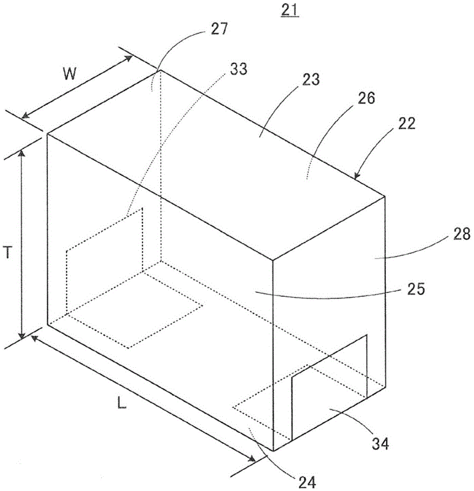
[0037] Such as figure 1 As shown, the coil component 21 of the first embodiment of the present invention includes a component main body 22 . The component main body 22 has a cubic shape and includes: a first main surface 23 and a second main surface 24 facing each other; The second side surface 26 , and the first end surface 27 and the second end surface 28 opposite to each other.

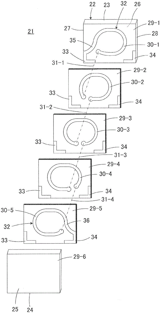
[0038] Such as figure 2 As shown, the component main body 22 has a laminated structure in which a plurality of insulator layers 29 are laminated in a direction perpendicular to the side surfaces 25 and 26 . In addition, in figure 2 The reference numerals on the insulator layer in , not only represent "29", but also represent "29-1", "29-2", ... "29-6". Here, when it is necessary to distinguish a plurality of insulator layers from each other, the reference numerals "29-1", "29-2", ... "29-6" are used, and there is no need to distinguish between a plurality of insulator layers. When layers ar...


PUM

PropertyMeasurementUnit
thicknessaaaaaaaaaa

Abstract

The invention provides a coil component in which a coil conductor is built in a laminated structure, and a higher inductance value and a Q value can be obtained. A central axis of the coil conductor (32) is oriented in parallel with a mounting surface. An external terminal electrode (33) is formed so as to extend from the bottom surface (a second main surface) (24) of a member main body (22) in an L-shape to the middle of an end surface (27). An extended conductor layer (35) connecting the external terminal electrode (33) and the coil conductor (32) is pulled out in a direction toward the upper surface (a first main surface) (23) from the end (37) of the external terminal electrode (33) in a state of forming identical end edges, with the distance larger than the distance extending in a normal line direction (NL) with respect to the outer peripheral edge of a circulating conductor layer (30) of the coil conductor (32) and equal to or smaller than the distance extending in a tangent line direction (TL) with respect to the outer peripheral edge of the circulating conductor layer (30), and connects the coil conductor (32) to the external terminal electrode (33).

Description

technical field [0001] The present invention relates to a coil component, and particularly relates to a coil component having a coil conductor embedded in a laminated structure. Background technique [0002] A coil component useful to the present invention is described in, for example, Japanese Patent No. 4220453 (Patent Document 1). Several examples of coil components called multilayer inductors are described in Patent Document 1, and a representative cross-sectional structure of them is shown in Figure 10 . [0003] refer to Figure 10 , the coil component 1 includes a component body 2 . The component main body 2 is in the shape of a cube, and includes: a first main surface 3 and a second main surface 4 facing each other; Two sides (with Figure 10 , but not shown), and the first end surface 5 and the second end surface 6 opposite to each other. [0004] A first external terminal electrode 7 and a second external terminal electrode 8 are respectively formed in a region...

Claims


Application Information

Patent Timeline
Patent Type & Authority Applications(China)
IPC IPC(8): H01F17/00H01F27/28H01F27/29
CPCH01F27/292H01F17/0013H01F17/0006H01F2017/0073
Inventor 小泽健
Owner MURATA MFG CO LTD
Why Eureka
Try Eureka