Dust removal and denitration integrated equipment for flue gas and filter box of dust removal and denitration integrated equipment

A denitrification and filter box technology, applied in gas treatment, dispersed particle filtration, chemical instruments and methods, etc., can solve problems such as high dust concentration, catalyst poisoning, catalyst module and air preheater erosion and wear

Pending Publication Date: 2017-01-04
FUJIAN LONGKING
View PDF5 Cites 1 Cited by
  • Summary
  • Abstract
  • Description
  • Claims
  • Application Information

AI Technical Summary

Problems solved by technology

[0004] (1) During denitrification, the flue gas contains a large amount of alkali metals, which is likely to cause catalyst poisoning;
[0005] (2) The dust concentration in the flue gas is high, which is easy to cause the erosion and wear of the catalyst module and the air preheater

Method used


Image

  • Dust removal and denitration integrated equipment for flue gas and filter box of dust removal and denitration integrated equipment
  • Dust removal and denitration integrated equipment for flue gas and filter box of dust removal and denitration integrated equipment
  • Dust removal and denitration integrated equipment for flue gas and filter box of dust removal and denitration integrated equipment

Examples


Embodiment Construction

[0043] In order to enable those skilled in the art to better understand the technical solutions of the present invention, the present invention will be further described in detail below in conjunction with the accompanying drawings and specific embodiments.

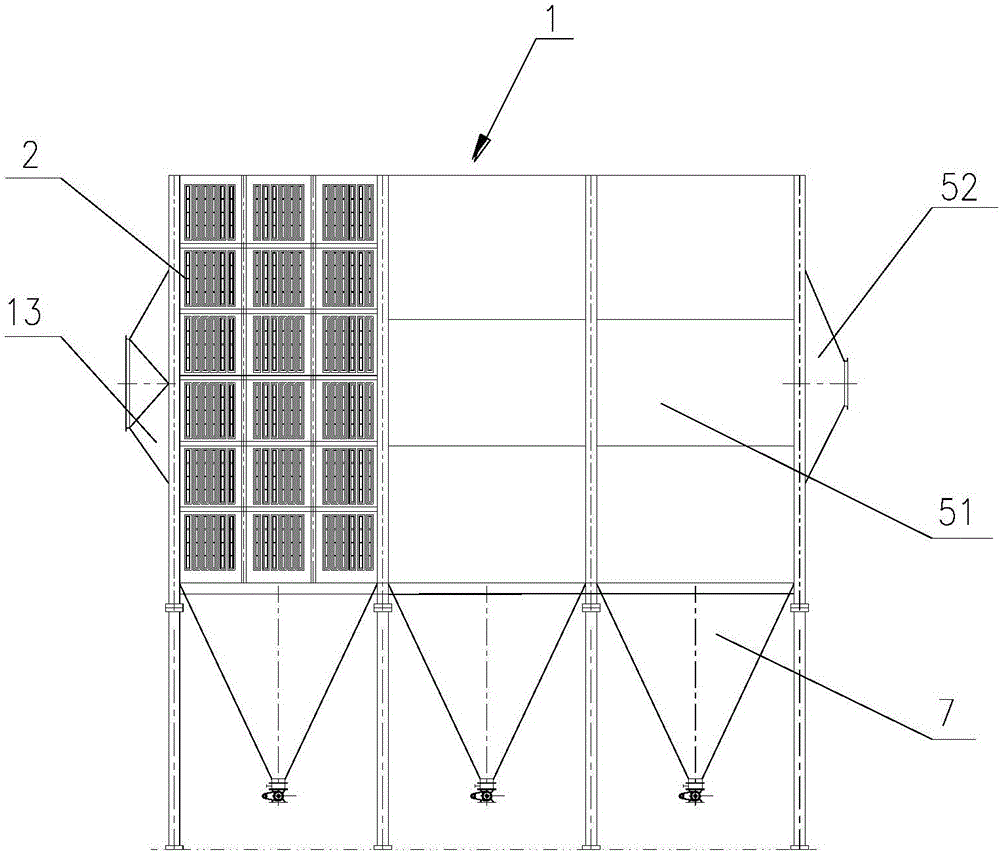
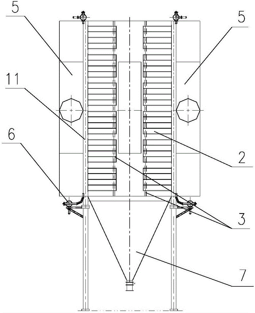
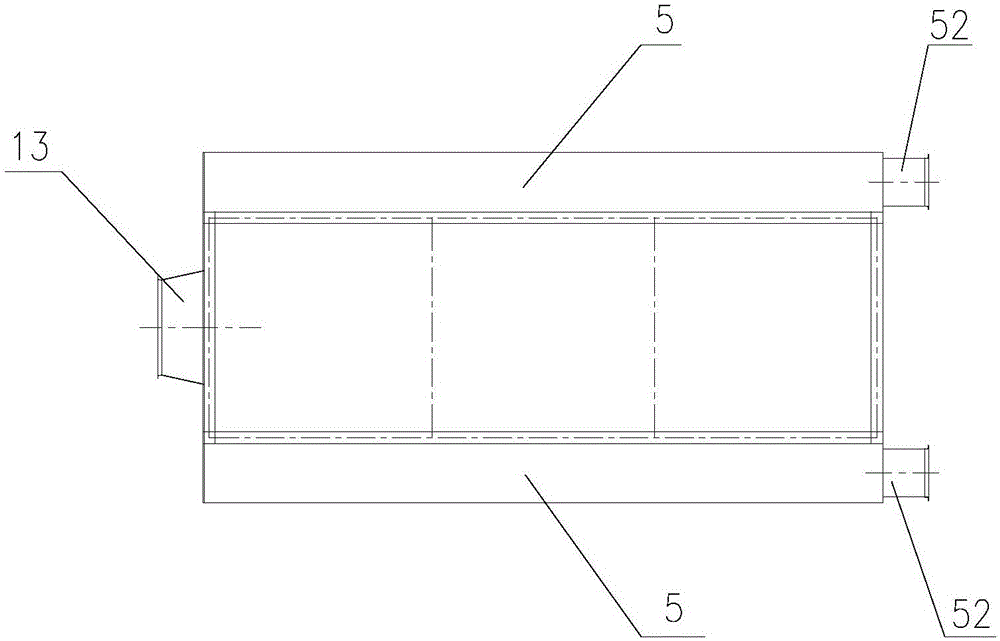
[0044] Please refer to the attached Figure 1-7 ,in, figure 1 Schematic diagram of the structure of the dust removal and denitrification integrated equipment provided by the present invention; figure 2 for figure 1 side view of image 3 for figure 1 top view of Figure 4 for figure 1 Schematic diagram of the filter box structure; Figure 5 for Figure 4 side view of Figure 6 for Figure 4 top view of Figure 7 for Figure 6 partial cutaway view.

[0045] In a specific embodiment, the present invention provides an integrated equipment for dust removal and denitrification of flue gas, such as figure 1 As shown, the dust removal and denitrification integrated equipment includes a housing 1, and the housing 1 i...


PUM


Abstract

The invention discloses dust removal and denitration integrated equipment for flue gas. The dust removal and denitration integrated equipment comprises a shell. A filter box is arranged in the shell and is provided with a dust removal portion and a denitration portion, and the flue gas can be denitrated by the denitration portion after dust in the flue gas is removed by the dust removal portion. The dust removal and denitration integrated equipment has the advantages that most alkali metal particles and the dust in the flue gas are removed before denitration reaction is carried out, and accordingly catalyst poisoning due to the alkali metal particles in the flue gas can be prevented; erosive wear of the denitration portion due to the dust in the flue gas can be prevented, accordingly, the denitration efficiency of the denitration portion can be improved, and the service life of the denitration portion can be guaranteed. The invention further discloses the filter box of the dust removal and denitration integrated equipment.

Description

technical field [0001] The invention relates to the technical field of flue gas dust removal, in particular to an integrated device for dust removal and denitrification of flue gas and a filter box thereof. Background technique [0002] At present, in domestic and foreign boiler flue gas purification systems, the denitration reactor and dust collector are set independently, and the denitration reactor is located before the dust collector, that is, during the flue gas treatment process, the denitration process is located before the dust removal process. The flue gas dust removal and denitrification process route based on the flue gas purification system is as follows: the 300-400 ℃ high temperature flue gas from the boiler economizer enters the denitrification reactor, and the flue gas after denitrification passes through the air preheater for heat exchange, and the temperature drops to 120-140°C, then enter the dust collector for dust removal. [0003] The above-mentioned f...

Claims


Application Information

Patent Timeline
Patent Type & Authority Applications(China)
IPC IPC(8): B01D53/88B01D53/86B01D53/56B01D46/00
CPCB01D53/8621B01D53/885B01D2258/0283B01D46/71
Inventor 黄星寇向上王妨赖栋文林荷刘颖
Owner FUJIAN LONGKING
Why Eureka
Try Eureka