Electronic element work unit and work equipment using electronic element work unit

A technology for electronic components and components, applied in the field of electronic component operation units, can solve the problems of consuming refrigeration energy costs, performing cold testing operations, and unable to maintain pre-cooling temperature, etc.

Active Publication Date: 2017-01-04
HON PRECISION INC
View PDF5 Cites 3 Cited by
  • Summary
  • Abstract
  • Description
  • Claims
  • Application Information

AI Technical Summary

Problems solved by technology

[0003] 1. Since the precooler 143 of the first carrier 14 has precooled the electronic components to be operated on the first storage tank 141 to a preset test temperature (such as -40 degrees), but the second material transfer device 15 During the process of transferring the pre-cooled electronic components, the electronic components are exposed to the surrounding environment above the machine 11, causing the pre-cooled electronic components to exchange heat with the surrounding air to heat up, and the pre-cooling temperature cannot be maintained , so that when the electronic components are placed in the test socket 161, the cold test operation cannot be performed according to the preset test temperature, thereby affecting the test quality
[0004] 2. During the process of transferring the pre-cooled electronic components by the second material transfer device 15, the pre-cooled ele

Method used


Image

  • Electronic element work unit and work equipment using electronic element work unit
  • Electronic element work unit and work equipment using electronic element work unit
  • Electronic element work unit and work equipment using electronic element work unit

Examples


Embodiment Construction

[0045] In order to make your examiner further understand the present invention, hereby give a preferred embodiment and cooperate with the drawings, as follows in detail:

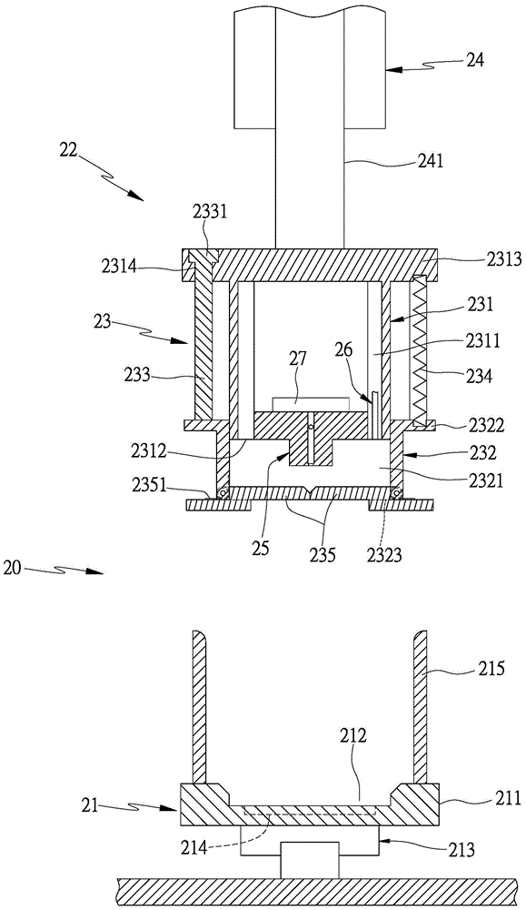
[0046] see image 3 The working unit 20 of the present invention includes a first holder 21 and a pick-up mechanism 22. The first holder 21 is provided with at least one holder for holding electronic components to be operated. The holder can be a carrier platform, material tray or test seat, etc., further, at least one first preheating member can be provided on the bearing member to precool or preheat the electronic components to be operated. In this embodiment, the first The holder 21 is provided with a first holder 211 which is a carrier, and the first holder 211 is provided with a first holder trough 212 to accommodate the electronic components to be operated. The conveying member 213 below the 211 is used to drive the first bearing member 211 to move in at least one direction (such as the first directio...


PUM


Abstract

The invention provides an electronic element work unit and work equipment using the electronic element work unit. A bearing device is provided with at least one bearing part. A picking mechanism drives at least one temperature maintaining structure to move to the position of the bearing device through a driving source. The temperature maintaining structure is provided with a temperature control box provided with a containing space. A door plank capable of being opened and closed is arranged at the position of an opening of the temperature control box. At least one control part capable of opening the door plank is arranged on the bearing device. At least one picking part is assembled in the temperature control box. When the control part abuts against the door plank to open the door plank, an electronic element about to work on the bearing device can be taken out. When the control part disengages from the door plank to close the door plank, the electronic element about to work is located in the sealed containing space of the temperature control box. A fluid supply device supplies fluid at the preset temperature to the containing space of the temperature control box. In the process that the picking mechanism transfers the electronic element about to work, the temperature maintaining structure can be used for preventing the electronic element from conducting cold and heat exchange with external air, the electronic element about to work maintains the preset temperature to execute work, and the purposes of improving the work quality and saving cost are achieved.

Description

technical field [0001] The invention relates to a method in which a pick-up mechanism transfers an electronic component to be operated. A temperature-maintaining structure can be used to prevent the electronic component from exchanging heat and cold with the outside air, so that the electronic component can maintain a preset temperature to perform the operation, so as to improve the operation quality and save energy. Cost of electronic components operating unit. Background technique [0002] Nowadays, electronic components may be in a low-temperature environment or a high-temperature environment when they are actually used. To ensure the quality of electronic components, after the electronic components are manufactured, they must use testing equipment to conduct cold or thermal tests on the electronic components. to weed out defective products; see figure 1 , figure 2 , is an electronic component testing and sorting machine, which is provided with a feeding device 12 with...

Claims


Application Information

Patent Timeline
IPC IPC(8): B07C5/36B07C5/02
Inventor 李子玮
Owner HON PRECISION INC
Why Eureka
Try Eureka