
Movable bending mechanism capable of facilitating discharging of large-bent-degree plates

A bending mechanism and mobile technology, applied in the direction of pushing out equipment, feeding devices, positioning devices, etc., can solve the problems of uneven bending quality, poor bending performance, and low work efficiency of plates, and meet the requirements of large batches. The effects of processing and production, avoiding excessive corner force deformation, and reasonable structural design

Inactive Publication Date: 2017-01-04
讯龙型材折弯(合肥)有限公司
View PDF6 Cites 1 Cited by
  • Summary
  • Abstract
  • Description
  • Claims
  • Application Information

AI Technical Summary

Problems solved by technology

[0004] In the prior art, the bending is carried out through the cooperation of the workbench and the bending mold. If the bending degree is relatively large, most of the plates are fed manually, and the manual feeding can only be fed in one direction, which affects the accuracy of the bending. And the quality of bending, this bending method has low work efficiency, uneven bending quality of the plate, poor performance at the bending place, and the plate is clamped between the workbench after bending, although it can be driven up and down by the oil cylinder The mold leaves, but because the plate is affected by the bending force when it is here, it is still difficult to take it out when it is close to the inner side of the workbench, and it is easy to deform if it is taken out forcibly, so it needs to be taken out by an auxiliary device, which is troublesome to operate and cannot meet mass processing production requirements

Method used


Image

  • Movable bending mechanism capable of facilitating discharging of large-bent-degree plates
  • Movable bending mechanism capable of facilitating discharging of large-bent-degree plates

Examples


Embodiment Construction

[0017] See attached picture.

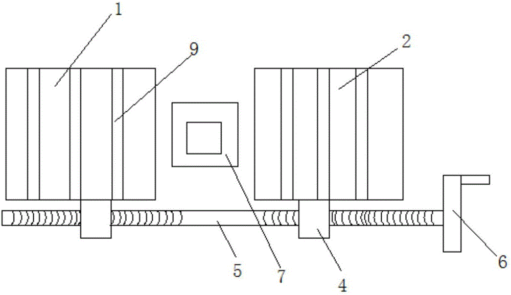
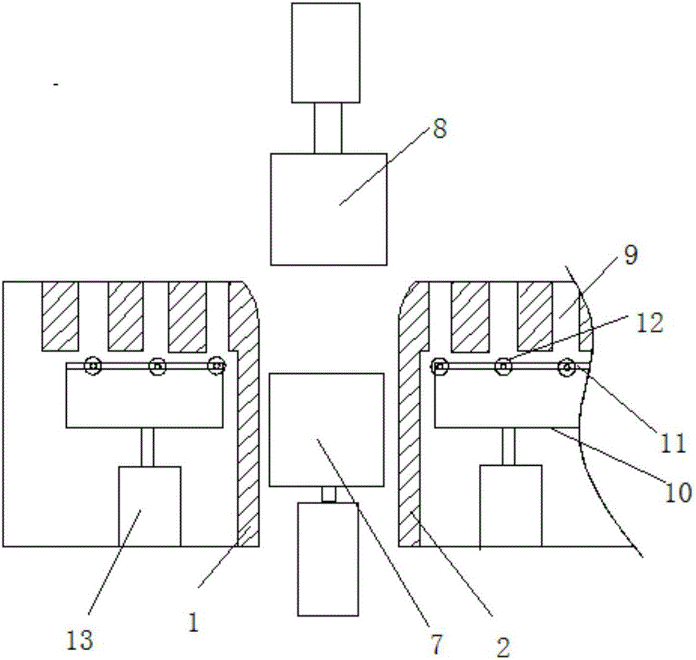
[0018] A movable bending mechanism that facilitates the discharge of large-bending plates, including movable left and right worktables 1 and 2 that are symmetrically matched at two intervals, and the movement of the left and right worktables 1 and 2 passes through its two sides Driven by a nut screw mechanism, the nut screw mechanism includes nuts 4 respectively arranged on the outside of the left and right workbenches, and a screw 5 is screwed into the nuts on the same side, and the helical direction of the screw 5 from the center to both ends is opposite, and The protruding end of the screw rod at the same end is equipped with a handwheel 6, a movable lower mold base 7 is arranged between the left and right workbenches 1 and 2, and an upper mold base 8 is arranged above the left and right workbenches 1 and 2, The upper end faces of the left and right workbenches 1 and 2 are respectively provided with guide grooves 9 along the plate conveying di...


PUM


Abstract

The invention discloses a movable bending mechanism capable of facilitating discharging of large-bent-degree plates. The movable bending mechanism comprises a left movable workbench and a right movable workbench which are matched symmetrically at an interval, the left workbench and the right workbench are driven to move by nut-screw mechanisms on two sides, the nut-screw mechanisms comprise nuts arranged on the outer sides of the left workbench and the right workbench respectively, screws are screwed into the nuts on the same sides, a movable die holder is arranged between the left workbench and the right bench, a punch holder is arranged above the left workbench and the right workbench, guide grooves are formed in the upper end faces of the left workbench and the right workbench along the plate conveying direction, movable U-shaped fixing frames are arranged in the left workbench and the right workbench below the guide grooves, two parallel fixing rods are mounted on U-shaped end ports of the U-shaped fixing frames, and guide rollers corresponding to the guide grooves are mounted on the fixing rods rotationally sequentially. The movable bending mechanism capable of facilitating discharging of the large-bent-degree plates is capable of machining the large-size plates, guaranteeing product quality and completing bending requirements automatically so as to meet the requirement on large-batch machining production.

Description

[0001] Technical field: [0002] The invention relates to the field of bending equipment, and mainly relates to a movable bending mechanism that facilitates the discharge of plates with a large bending degree. [0003] Background technique: [0004] In the prior art, the bending is carried out through the cooperation of the workbench and the bending mold. If the bending degree is relatively large, most of the plates are fed manually, and the manual feeding can only be fed in one direction, which affects the accuracy of the bending. And the quality of bending, this bending method has low work efficiency, uneven bending quality of the plate, poor performance at the bending place, and the plate is clamped between the workbench after bending, although it can be driven up and down by the oil cylinder The mold leaves, but because the plate is affected by the bending force when it is here, it is still difficult to take it out when it is close to the inner side of the workbench, and it...

Claims


Application Information

Patent Timeline
IPC IPC(8): B21D5/06B21D43/08B21D45/02
CPCB21D5/06B21D43/08B21D45/02
Inventor 伍红梅
Owner 讯龙型材折弯(合肥)有限公司
Learn More