Cold upsetting forming method for power supply pin

A molding method and pin technology, applied in steering mechanism, connecting rod, mechanical equipment and other directions, can solve the problems of high material cost, low production efficiency and high processing cost, achieve high material utilization rate, improve production efficiency and reduce material cost Effect

Active Publication Date: 2017-01-04
上海顺翼紧固件有限公司
View PDF4 Cites 6 Cited by
  • Summary
  • Abstract
  • Description
  • Claims
  • Application Information

AI Technical Summary

Problems solved by technology

In the existing technology, the pins for power plugs are generally made of profiles, which are processed by ordinary punching machines, machining tools, machining centers and other equipment. The complex process, low production efficiency, and insufficient material utilization rate lead to high material costs. , high processing cost, low strength, etc.

Method used


Image

  • Cold upsetting forming method for power supply pin
  • Cold upsetting forming method for power supply pin
  • Cold upsetting forming method for power supply pin

Examples


Embodiment Construction

[0027] The preferred embodiments of the present invention are given below in conjunction with the accompanying drawings to describe the technical solution of the present invention in detail.

[0028] The cold heading forming method of the power pin of the present invention comprises the following steps:

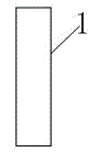
[0029] Step 1, intercept the blank ( figure 1 ), is to apply the intermittent stepping automatic material cutting system, which automatically cuts out a reasonable length of the blank 1 from the coiled wire material whose diameter is close to the circumscribed circle of the power pin body or the coiled wire material with a reasonable strength beam ratio, and automatically The feeding system is synchronously transported to the cold extrusion station of the multi-stroke cold heading machine; the shape of the blank 1 can be a cylinder, which is automatically intercepted by the coil wire for cold heading.

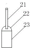
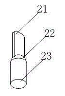
[0030] Step 2, the diameter of the power pin body is reduced and preform...


PUM

PropertyMeasurementUnit
radiusaaaaaaaaaa

Abstract

The invention discloses a cold upsetting forming method for a power supply pin. The cold upsetting forming method for the power supply pin includes the following steps that first, a blank is cut out; second, a power supply pin body is necked and preformed; third, a pin fixing disk is preformed; and fourth, the power supply pin is integrally formed. The cold upsetting forming method is simple in process, high-speed and automatic production is realized, production efficiency is high, the material utilization rate is increased, and the strength is improved.

Description

technical field [0001] The invention relates to a cold heading forming method, in particular to a cold heading forming method of a power supply pin. Background technique [0002] With the improvement of social living standards, communications, electronics, household appliances, automobiles, etc. have become the most common products that enrich people's lives, such as intelligent mobile phones, TVs, refrigerators, electric tools, etc., and the plugs connected to the power supply have been widely used. application. In the existing technology, the pins for power plugs are generally made of profiles, which are processed by ordinary punching machines, machining tools, machining centers and other equipment. The complex process, low production efficiency, and insufficient material utilization rate lead to high material costs. , high processing cost, low strength, etc. Contents of the invention [0003] The technical problem to be solved by the present invention is to provide a ...

Claims


Application Information

Patent Timeline
Patent Type & Authority Applications(China)
IPC IPC(8): B21J5/08
CPCB21D53/84B21J5/00B21K1/766B62D7/20F16C7/02
Inventor 周满志宋广东
Owner 上海顺翼紧固件有限公司
Why Eureka
Try Eureka