Guide blade edge plate dustpan hole machining rapid changing clamping device and method

A technology of guide vane and clamping device, which is applied in the direction of accessory devices, electric processing equipment, metal processing equipment, etc., can solve the problems of complex clamping structure, inconvenient operation, and many angles involved in the dustpan hole, so as to achieve convenient operation and improve replacement. Model efficiency, compact structure effect

Active Publication Date: 2017-01-04
AECC AVIATION POWER CO LTD
View PDF10 Cites 9 Cited by
  • Summary
  • Abstract
  • Description
  • Claims
  • Application Information

AI Technical Summary

Problems solved by technology

Due to the special shape of the dustpan hole, it is generally processed by EDM electrodes. The dustpan hole involves many angles. The traditional split clamping s

Method used


Image

  • Guide blade edge plate dustpan hole machining rapid changing clamping device and method
  • Guide blade edge plate dustpan hole machining rapid changing clamping device and method
  • Guide blade edge plate dustpan hole machining rapid changing clamping device and method

Examples


Embodiment Construction

[0046] The present invention will be further described below in conjunction with the accompanying drawings.

[0047] The purpose of the present invention is to design a fast-changing clamping device for machining the dustpan hole of the edge plate of the guide vane, so as to reduce the labor intensity and improve the processing efficiency.

[0048] The purpose of this method is to realize by following steps:

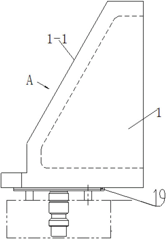
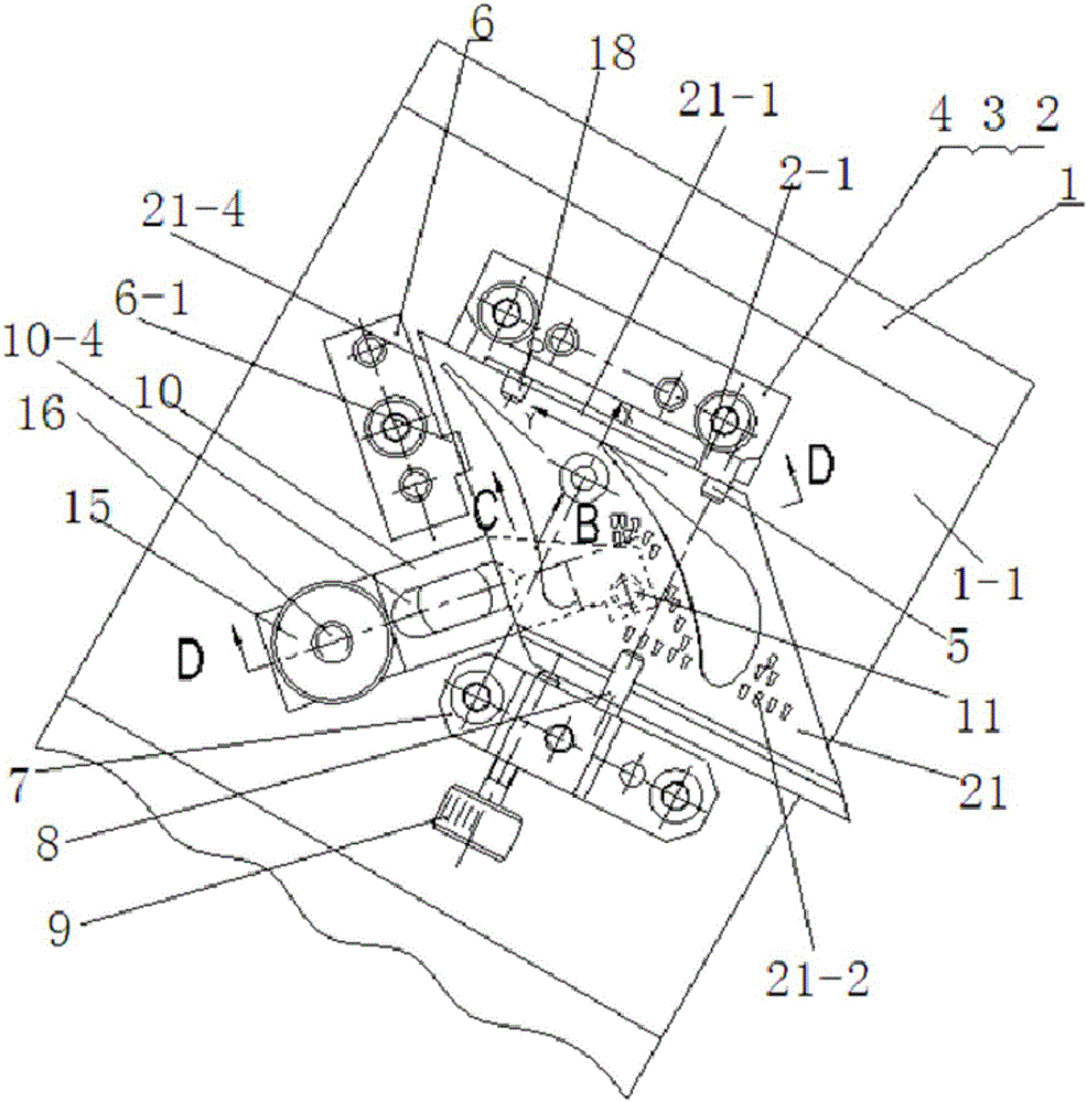
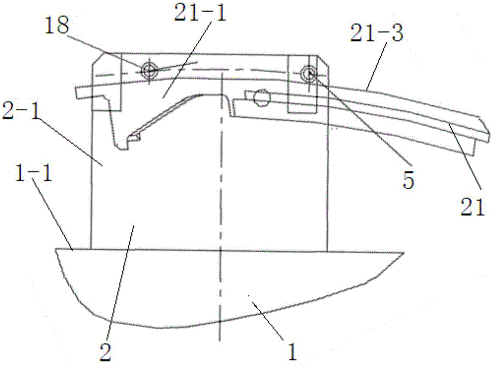
[0049] 1) Design an integral clamping structure, and directly design the upper positioning point on the body 1 to save space.

[0050] 2) In tooling design, the technology based on 3D solid design is used to reversely design the fixture body directly from the UG shape of the guide vane edge plate 21, and directly perform structural weight reduction optimization on the solid model of the fixture to make the volume small enough.

[0051] 3) Except for the clamping and positioning components, the other components including the clamping device body 1 are all made of cast al...


PUM


Abstract

The invention belongs to the field of machining of aero-engine turbine guide blades, and relates to a guide blade edge plate dustpan hole machining rapid changing clamping device and method. The clamping device is in a whole type, a positioning block and a supporting plate are arranged on the angular face of a clamping device body, the direction of a guide blade edge plate is positioned through a positioning face on the positioning block, through two positioning pins on the positioning block and one positioning pin on the supporting plate, positioning of the circular-arc top face of the guide blade edge plate in the vertical height direction is achieved, and the guide blade edge plate is jacked upwards from the lower portion of the guide blade edge plate through a jacking mechanism so that the guide blade edge plate is clamped; the exhaust side end face and the positioning face of the positioning block are attached, the guide blade edge plate is jacked upwards by adjusting the jacking mechanism, the circular-arc top face of the guide blade edge plate is tightly attached to the first positioning pin, the second positioning pin and the third positioning pin, a uniform gap is arranged between the exhaust side end face and the positioning face, and the beneficial effects of being compact in structure and rapid and convenient to operate are achieved.

Description

[0001] 【Technical field】 [0002] The invention belongs to the field of machining turbine guide vanes of aero-engines, and in particular relates to a fast-changing clamping device and method for machining a dustpan hole on an edge plate of a guide vane. [0003] 【Background technique】 [0004] In order to improve the cooling effect of the turbine guide vanes of aero-engines, the upper and lower edge plates of the guide vanes are often designed with a large number of dustpan-shaped air film holes to meet the cooling requirements. Due to the special shape of the dustpan hole, it is generally processed by EDM electrodes. The dustpan hole involves many angles. The traditional split clamping structure is complicated, the operation is inconvenient, and the changeover time exceeds 1 hour, which cannot meet the batch production of guide blade edge plates. . [0005] The relevant content of the present invention is by searching the relevant content of the present invention on the websi...

Claims


Application Information

Patent Timeline
IPC IPC(8): B23H11/00B23H9/14
CPCB23H9/14B23H11/003
Inventor 张澜禹李绍鹏刘海滨温学兵王冬朱爱芝
Owner AECC AVIATION POWER CO LTD
Why Eureka
Try Eureka