Motion planning method for additional shafts in working units of gantry hoisting robot

A work unit and motion planning technology, which is applied in the direction of manipulators, manufacturing tools, program control manipulators, etc., can solve the problems of large range of robot joint changes, and achieve the effect of improving work adaptability, reducing joint changes, and continuous and stable motion

Active Publication Date: 2017-01-04
SHANGHAI UNIV
View PDF6 Cites 6 Cited by
  • Summary
  • Abstract
  • Description
  • Claims
  • Application Information

AI Technical Summary

Problems solved by technology

[0003] According to the literature search of the existing technology, it is found that there is a sub-station task planning and control method for controlling the motion mode of the robot’s additional axis, that is, the robot only works at a few specific stations of the additional axis. Although this method can realize the control of the product The coverage of the entire processing range, but when processing the continuous trajectory points within the corresponding processing range at a certain station, the joints of the robot itself change greatly, and when it is necessary to process the processing range corresponding to the next station, it is necessary to wait for the robot to start from a station. Move to another site, so this method is suitable for relatively discrete trajectory points on large workpieces, such as automatic drilling and riveting based on industrial robots

Method used


Image

  • Motion planning method for additional shafts in working units of gantry hoisting robot
  • Motion planning method for additional shafts in working units of gantry hoisting robot
  • Motion planning method for additional shafts in working units of gantry hoisting robot

Examples


Embodiment Construction

[0031] The following takes the Fanuc 1-M-20iA model robot as an example, and the embodiments of the present invention are described in detail with reference to the accompanying drawings.

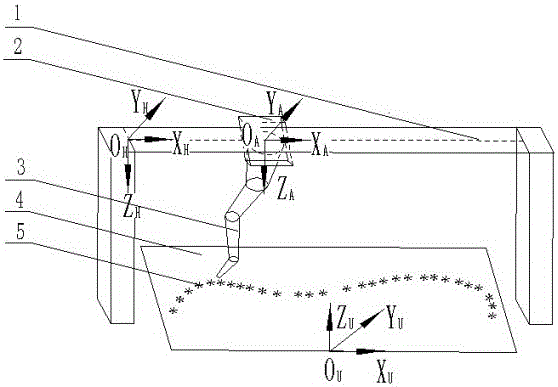
[0032] Such as figure 1 As shown, the gantry hoisting robot working unit is composed of linear guide 1, sliding table 2, industrial robot 3, work table 4, and processing track point 5.

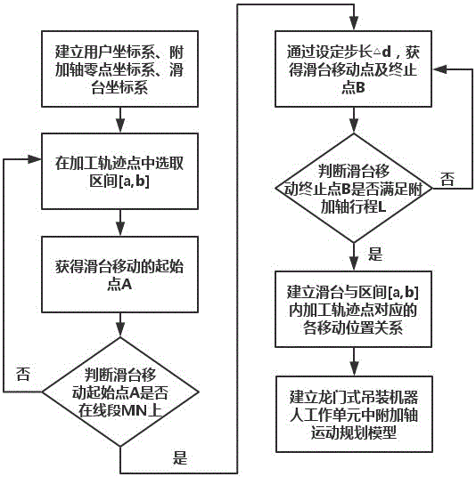
[0033] Such as figure 2 As shown, an additional axis motion planning method in a gantry hoisting robot work unit, the additional axis includes a linear guide rail and a sliding table, and includes the following steps:

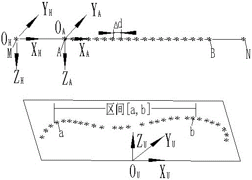
[0034] The first step: such as image 3 As shown, the user coordinate system {O U X U Y U Z U }; Establish the guideway zero point coordinate system at the linear guideway zero point M {O H X H Y H Z H }, OX axis direction is the movement direction of the sliding table (that is, the axis direction of the guide rail); the sliding table coordinate system is established at the center of the lower...


PUM


Abstract

The invention relates to a motion planning method for additional shafts in working units of a gantry hoisting robot. On the basis of addition of the gantry external linear additional shafts, redundant working units linked with six joints of the industrial robot, and a fixed working platform, two of a section of machining path points monotonously changing along a motion direction of each slide table which is fixedly connected with a robot base on the corresponding additional shaft are manually selected as end points of a preferred interval. A movable initial point of each slide table is obtained through a projection principle of a straight line from a point to a space. A movable middle point and a movable termination point of each slide table are obtained through setting a step length of the slide table, that is, distances from movable positions corresponding to the machining path points in the corresponding preferred interval, of each slide table, to a zero point of the corresponding additional shaft, are obtained. Movements of the slide tables are in preference to motions of the joints of the robot when the robot machines the path points in the preferred intervals. The method is capable of reducing the change amplitudes of the joints of the robot, so that the motion of the robot is continuous and stable; and the method is suitable for machining the continuous and dense path points by the robot.

Description

Technical field [0001] The invention relates to an additional axis motion planning method in a gantry type hoisting robot work unit, and belongs to the field of industrial robot redundant work space control. Background technique [0002] As industrial robots are gradually being widely used in industrial production, the need to expand the processing range of industrial robots has become increasingly prominent. In many robot applications, such as large-scale mold chamfering surface induction hardening systems based on industrial robots, due to the large size of the work object, it is necessary to add an external linear additional axis to the industrial robot to expand the robot's working range. In addition, the robot is mounted upside down on the gantry-type additional axis, which can be effectively applied to the robot installation area that cannot be used in the past. [0003] The literature search of the prior art found that the current control robot additional axis motion mode h...

Claims


Application Information

Patent Timeline
Patent Type & Authority Applications(China)
IPC IPC(8): B25J9/16
CPCB25J9/1612B25J9/1615B25J9/1664
Inventor 沈南燕鞠然李静钱晖禹壮童梁
Owner SHANGHAI UNIV
Why Eureka
Try Eureka