Method for automatically partitioning complicated section zone during additive manufacturing

A regional and complex technology, applied in the field of additive manufacturing, to achieve the effect of reducing the number of knife lifts and improving printing efficiency

Active Publication Date: 2017-01-04
DALIAN UNIV OF TECH
View PDF8 Cites 17 Cited by
  • Summary
  • Abstract
  • Description
  • Claims
  • Application Information

AI Technical Summary

Problems solved by technology

[0003] Aiming at the problem of optimizing the segmentation of complex slice areas with shape features such as holes, the invention provides an automatic segmentation method for complex slice areas in additive manufacturing technology

Method used


Image

  • Method for automatically partitioning complicated section zone during additive manufacturing
  • Method for automatically partitioning complicated section zone during additive manufacturing
  • Method for automatically partitioning complicated section zone during additive manufacturing

Examples


Embodiment

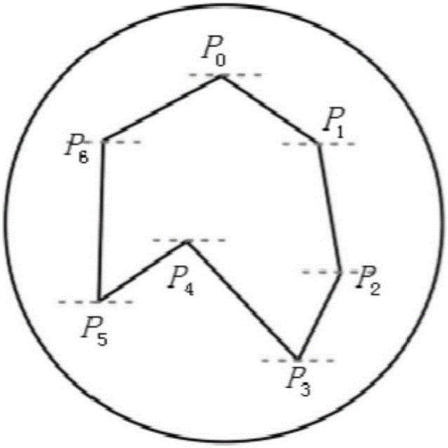
[0022] (1) Discrimination of region segmentation points:

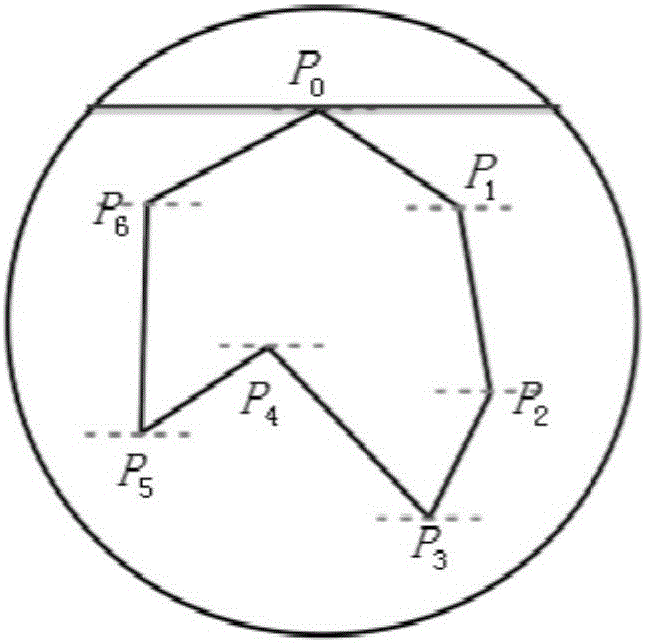
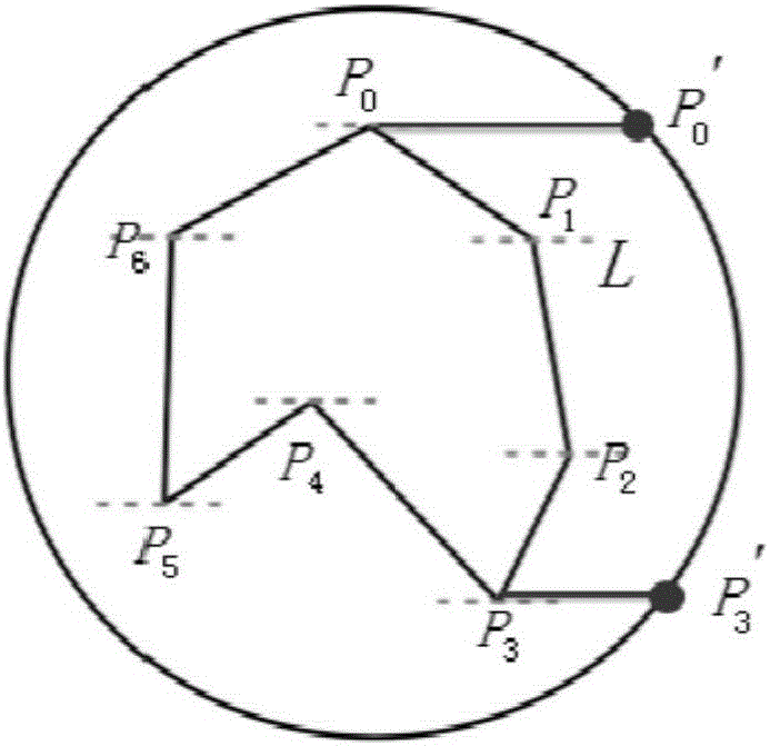
[0023] figure 1 In the hole structure whose inner contour is a concave polygon, it consists of P 0 ~P 6 A total of seven coordinate points are formed, and the line connecting two data points with adjacent subscript index values ​​constitutes the edge of the inner contour. According to the above region segmentation point discrimination algorithm, by P 0 ~P 6 Each vertex of the inner contour is examined in turn. to examine P 0 For example, P 0 The next point of the adjacent index value is P 1 , the y coordinate values ​​of the two are not equal, that is, P 0 P 1 Not a horizontal edge. with P 0 The adjacent inner contour vertices are P 1 ,P 6 , over P 0 Points to draw a horizontal line L, such as figure 2 , it is not difficult to find that P 1 ,P 6 Two points are on the same side of the horizontal line L, then P 0 as a possible split point. At this point, first from P 0 Point out the ray to the right,...


PUM


Abstract

The invention provides a method for automatically partitioning a complicated section zone in an additive manufacturing technology and belongs to the field of additive manufacturing. The method comprises the steps that a complicated cross-section outline with holes is divided into a plurality of simple inner-hole-free sub-zones. Continuous printing in each sub-zone can be completed without cutter lifting. After zone partitioning, the zones are independently processed, and the cutter lifting only occurs in the zone connecting process. Therefore, the phenomenon that a simple parallel scanning route needs to step over the inner hole zones of non-processing routes for multiple times is avoided. The method aims at the complicated section zone having holes and other shape characteristics, the problem of section zone partitioning optimization due to the fact that a target is the minimum idle stroke of a mechanism is solved, and optimization of scanning route tracks is achieved. The section zone partitioning method adopts a partitioning point distinguishing algorithm, a zone partitioning cross point algorithm and a zoned outline information storage algorithm. The phenomenon that the simple parallel scanning route needs to step over the inner hole zones of non-processing routes for multiple times can be avoided, and accordingly the additive manufacturing efficiency can be improved.

Description

technical field [0001] The invention relates to a method for automatically segmenting complex slicing regions in additive manufacturing technology, and belongs to the technical field of additive manufacturing. Background technique [0002] Additive manufacturing technology, also known as 3D printing, is a research hotspot in the field of manufacturing in recent years, but due to the current processing efficiency of 3D printing, it is determined that this manufacturing technology is more suitable for the production of personalized products and small batch products. How to improve the production efficiency and molding speed of additive manufacturing technology has also become an important problem to be solved urgently. 3D printing processing is a process of accumulating and manufacturing materials layer by layer. When the 3D printing model is layered and sliced, the slice layer contains structures such as holes and holes. At this time, the generated processing trajectory needs...

Claims


Application Information

Patent Timeline
Patent Type & Authority Applications(China)
IPC IPC(8): B29C67/00B33Y50/00
CPCB33Y50/00
Inventor 侯文彬徐金亭侯少强夏明栋
Owner DALIAN UNIV OF TECH
Why Eureka
Try Eureka