
Detecting head for electronic yarn cleaner
A technology of electronic yarn clearer and detection head, which is applied in the direction of textile and paper making, and can solve the problems of surface acoustic wave signal attenuation, slow touch, inconvenient installation and use, etc.
- Summary
- Abstract
- Description
- Claims
- Application Information
AI Technical Summary
Problems solved by technology
Method used
Image

Examples
Embodiment 1
[0049] Electronic yarn clearer detection head, including a touch button;
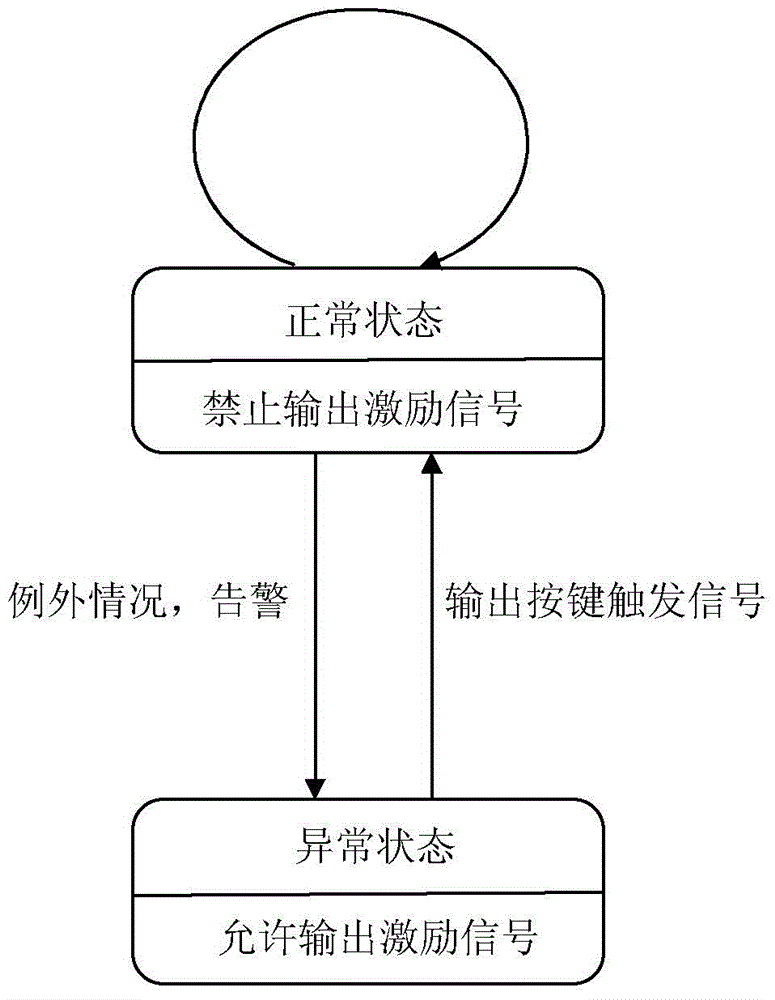
[0050]The detection head of the electronic yarn clearer has at least two states of normal and abnormal;
[0051] The touch key is a photoelectric touch key, including a light transmitter, a light receiver, and a microprocessor;
[0052] The light emitter is used to emit light of a specific wavelength;
[0053] The optical receiver is configured to output an electrical signal according to the received light;
[0054] In the optical receiver, the sensitive wavelength matches the wavelength of the light emitted by the optical transmitter;
[0055] The microprocessor outputs an excitation signal to the light emitter, controls the light emitter to emit light, and outputs a button trigger signal according to the electrical signal from the light receiver;
[0056] The microprocessor, when the detection head of the electronic yarn clearer is in a normal state, prohibits the output of the excitation signal to...
Embodiment 2
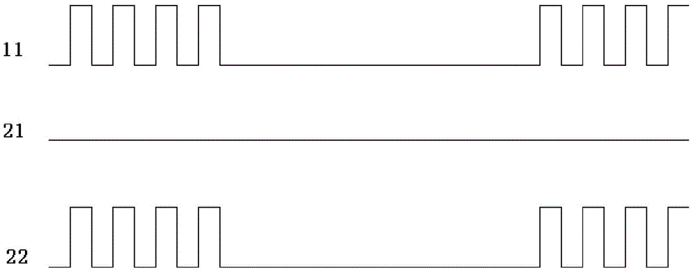
[0066] Based on the detection head of the electronic yarn clearer in Embodiment 1, the excitation signal is a pulse signal.
[0067] Preferably, the excitation signal is a pulse signal of 5KHz to 10KHz.
[0068] Preferably, the excitation signal is a pulse signal with a duty cycle less than or equal to 50%. The duty cycle refers to the ratio of the energization time of the pulse signal to the energization period. In a series of ideal pulse cycle sequences (such as square waves), the duty cycle is the ratio of the duration of the positive pulse to the total cycle of the pulse.
[0069] Preferably, a band-pass filter circuit is provided between the optical receiver and the microprocessor;
[0070] The band-pass filter circuit is used to filter out low-frequency interference and high-frequency interference beyond the passband in the electrical signal output by the optical receiver.
[0071] The detection head of the electronic yarn clearer in the second embodiment, because the...
Embodiment 3
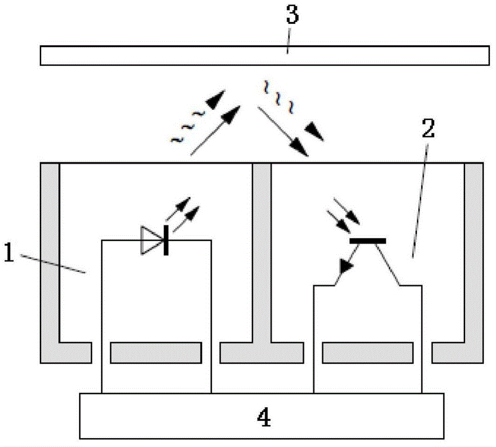
[0073] Based on the electronic yarn clearer detection head of embodiment one or embodiment two, the touch button, such as figure 2 As shown, it includes an optical transmitter 1, an optical receiver 2, a microprocessor 4, and a housing;
[0074] The housing includes a left accommodating area and a right accommodating area;
[0075] The left accommodation area and the right accommodation area, the upper end is transparent, and the side wall and bottom are opaque;
[0076] The light transmitter 1 is placed in the left accommodating area, and emits light of a specific wavelength according to the excitation signal transmitted from the microprocessor 4;
[0077] The optical receiver 2 is placed in the right accommodation area, and outputs a corresponding electrical signal to the microprocessor 4 according to the received light of the sensitive wavelength; the sensitive wavelength of the optical receiver 2 is the same as that of the optical transmitter 1 The wavelength of the emi...
PUM
 Abstract
Description
Claims
Application Information