Steel bar connector capable of adjusting position on plane

A technology of steel bar connectors and planes, which is applied to structural elements, building components, building reinforcements, etc., can solve problems such as the inability to connect steel bars, slow assembly and construction progress, and heavy connection workload, so as to achieve simple and convenient connection methods and reduce The effect of labor intensity and work efficiency improvement

Inactive Publication Date: 2017-01-04
HARBIN INST OF TECH
View PDF6 Cites 3 Cited by
  • Summary
  • Abstract
  • Description
  • Claims
  • Application Information

AI Technical Summary

Problems solved by technology

[0003] In order to solve the problems of heavy connection workload, slow assembly and construction progress in the existing prefabricated concrete house steel bar connection, and at the same time, the connection cannot be realized with misaligned steel bars, the present invention further proposes a steel bar connector with adjustable position on the plane

Method used


Image

  • Steel bar connector capable of adjusting position on plane
  • Steel bar connector capable of adjusting position on plane
  • Steel bar connector capable of adjusting position on plane

Examples


specific Embodiment approach 1

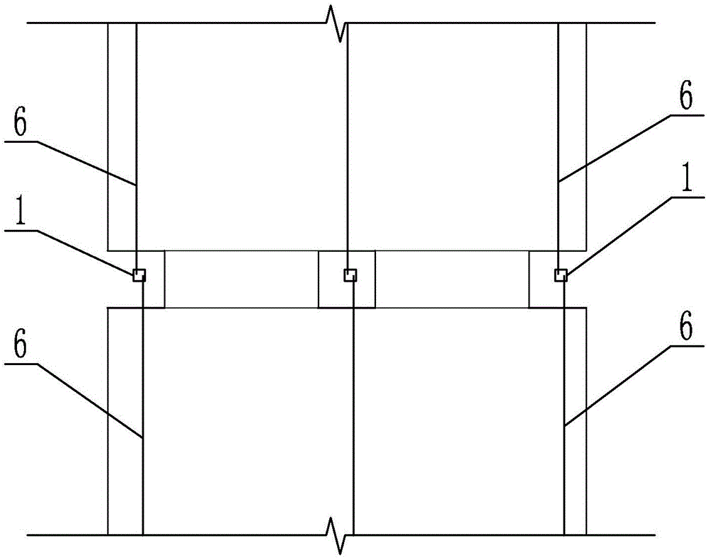
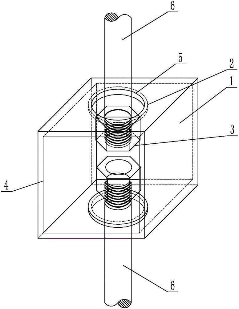
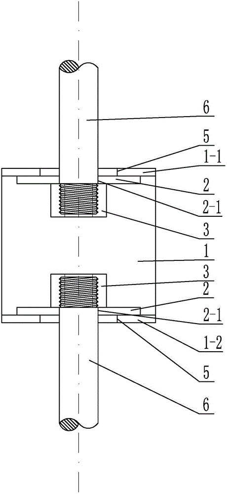
[0012] Specific implementation mode one: combine Figure 1 to Figure 5 This embodiment is described. A plane-adjustable steel bar connector described in this embodiment includes a connection frame 1, two limit bottom plates 2 and two nuts 3, and the upper end surface 1-1 and the lower end surface 1 of the connection frame 1 -2 are respectively arranged horizontally, the front end face and the rear end face of the connecting frame 1 are provided with an installation port 4, and the middle parts of the upper end face 1-1 and the lower end face 1-2 are respectively provided with a connecting through hole 5, and the reinforcing bars 6 on the upper part are vertical Inserted in the connection through hole 5 of the upper end surface 1-1, the lower steel bar 6 is vertically inserted in the connection through hole 5 of the lower end surface 1-2, and the ends of the upper and lower two steel bars 6 are respectively screwed with nuts 3, the nuts 3 Set in the connection frame 1, between ...

specific Embodiment approach 2

[0014] Specific implementation mode two: combination Figure 2 to Figure 5 To describe this embodiment, the shape of the connecting frame 1 in this embodiment is rectangular. The undisclosed technical features in this embodiment are the same as those in the first embodiment.

[0015] Such a design can change the shape and size of the connecting frame 1 as required, and the shape requires symmetry, which is easy to manufacture, and has a certain strength, which can ensure the bearing capacity of the joint.

specific Embodiment approach 3

[0016] Specific implementation mode three: combination Figure 2 to Figure 5 To describe this embodiment, the diameter of the connecting through hole 5 in this embodiment is larger than the outer diameter of the steel bar 6 . The undisclosed technical features in this embodiment are the same as those in the first or second specific embodiment.

[0017] This design can realize the in-plane movement of the steel bars 6, and when the longitudinal geometric center of the steel bars 6 is inconsistent with the geometric center of the connector, the steel bars 6 can be connected to the connectors respectively, thereby realizing the connection of the steel bars 6 at both ends.


PUM


Abstract

The invention provides a steel bar connector capable of adjusting the position on the plane, and relates to the field of civil engineering. The problems that existing precast fabricated concrete building steel bar connection is high in connection workload and slow in fabricated construction progress, and meanwhile connection cannot be achieved without aligning steel bars are solved. The steel bar connector capable of adjusting the position on the plane comprises a connection frame, two limiting base plates and two nuts, the upper end face and the lower end face of the connection frame are horizontally arranged respectively, the front end face and the rear end face of the connection frame are each provided with an installation port, the middle of the upper end face and the middle of the lower end face are each provided with a connection through hole, the steel bar on the upper portion is vertically inserted into the connection through hole of the upper end face, the steel bar on the lower portion is vertically inserted into the connection through hole of the lower end face, the nuts are installed at the tail ends of the steel bars in a screwed mode respectively, the nuts are arranged in the connection frame, the limiting base plates are arranged between the nut located at the upper end and the upper end face and between the nut located at the lower end and the lower end face respectively, and the limiting base plates are installed outside the steel bars in a sleeving mode. The steel bar connector capable of adjusting the position on the plane is used for building construction.

Description

technical field [0001] The invention relates to the field of civil engineering, in particular to a steel bar connector whose position can be adjusted on a plane. Background technique [0002] At present, nodular cast iron grouting sleeve connection, semi-grouting sleeve connection and restrained grout anchor lap connection are often used to connect the steel bars of prefabricated concrete houses. These connection methods have prominent problems such as large connection workload and slow assembly construction progress; the upper and lower floors When the prefabricated vertical components are assembled vertically, it is difficult to align the longitudinal reinforced steel bars of the vertical components accurately. Contents of the invention [0003] In order to solve the problems that existing prefabricated concrete houses have heavy connection workload, slow assembly and construction progress, and inability to realize connection of misaligned steel bars, the present inventi...

Claims


Application Information

Patent Timeline
Patent Type & Authority Applications(China)
IPC IPC(8): E04C5/16
CPCE04C5/165
Inventor 郑文忠周威侯晓萌王英
Owner HARBIN INST OF TECH
Why Eureka
Try Eureka