Earth pressure balance shield driving parameter control method based on earth surface deformation

A technology of earth pressure balance shield and tunneling parameters, which is applied in earth-moving drilling, mining equipment, tunnels, etc., and can solve the problems of numerical difference, delayed feedback of surface settlement information, and inability to quantitatively evaluate the relationship between face pressure and formation response.

Active Publication Date: 2017-01-04
CENT SOUTH UNIV
View PDF2 Cites 21 Cited by
  • Summary
  • Abstract
  • Description
  • Claims
  • Application Information

AI Technical Summary

Problems solved by technology

This method has three shortcomings. The first is that the control of shield tunneling parameters depends to a large extent on the shield driver's operating skills and operating experience in similar formations and buried depths; the second is the feedback of surface settlement information. Too late, when the shield driver gets the information to change the tunneling parameters, excessive settlement or uplift has already occurred. In cities with dense pipelines and many buildings (structures), the feedback process is slow and may cause excessive losses; the third disadvantage is tunneling The control process is similar to a black box behavior, and there is neither a guiding basis for the tunneling process nor a clear range of tunneling parameters
There are two problems in the method of controlling earth pressure to realize excavation control: Problem 1 is that due to the complexity of the stress state in the soil bin and the difficulty in measuring the earth pressure on the face of the tunnel, the measurement of earth pressure is generally done by installing an earth pressure cell on the partition of the soil bin Completed, but there is a large diffe

Method used


Image

  • Earth pressure balance shield driving parameter control method based on earth surface deformation
  • Earth pressure balance shield driving parameter control method based on earth surface deformation
  • Earth pressure balance shield driving parameter control method based on earth surface deformation

Examples


Embodiment Construction

[0041] The present invention will be further described below in conjunction with accompanying drawing.

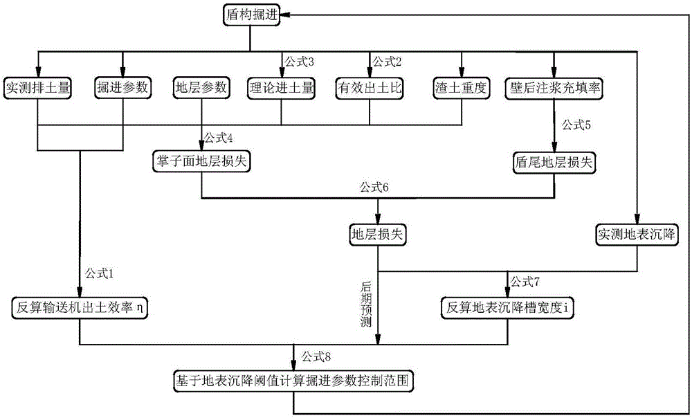
[0042] see figure 1 , a parameter control method for earth pressure balance shield tunneling based on surface deformation, including the following steps:

[0043] Step (1): When the shield tunneling process is in progress and the pressure of the soil bin begins to stabilize, measure the volume V and weight G of the muck discharged from the shield within the time T of one ring segment, and divide the weight G of the muck by the weight of the dregs Soil volume V, get the weight of muck γ 1 ;Record the excavation speed v, the screw conveyor speed N, and the added weight of the slag improvement material G 1 ;

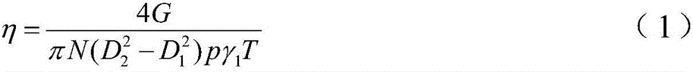
[0044] Step (2): Combining the gravity G of the muck discharged by the screw conveyor during shield tunneling and the parameters of the shield itself, namely the thread pitch P and the diameter of the screw mandrel D 1 and the inner diameter of the screw machine D 2...


PUM


Abstract

The invention discloses an earth pressure balance shield driving parameter control method based on earth surface deformation. Calculation formulas of shield earth pressure balance ratio (N/v) and ground loss caused by shield dumping are built in a deduced manner, ground loss caused by shield tail void is considered, spiral conveyer dumping efficiency eta and earth surface settlement trough width I are reversely calculated by the aid of driving data of a shield at the initial driving stage and earth surface settlement data, a control range of the earth pressure balance ratio (N/v) of the shield at next driving stage is built, a reasonable control basis is provided for next driving speed of the shield and spiral conveyer rotating speed according to the range, and procedures are repetitively calculated in next driving process. The earth pressure balance shield driving parameter control method is simple and practical, a quantitatively clear control range can be provided for the driving speed of the shield and the spiral conveyer rotating speed, the problems of overlarge settlement and upheaval of earth surface caused by driving of a tunnel boring machine can be effectively solved.

Description

technical field [0001] The invention relates to a parameter control method of earth pressure balance shield tunneling, in particular, the invention relates to a control method of soil pressure balance shield tunneling parameters based on surface deformation. Background technique [0002] As one of the important construction methods for tunnel excavation in soft ground, the earth pressure balance shield method is widely used in the construction of subways in major cities at home and abroad. Due to insufficient understanding of earth pressure balance shield excavation and stratum response, excessive surface uplift and subsidence caused by current construction often occur. [0003] The current research on the balance control theory of earth pressure balance shields basically focuses on the feedback of the soil chamber pressure, that is, the amount of soil entering and discharging of the shield is controlled by controlling the pressure of the earth chamber of the shield. The st...

Claims


Application Information

Patent Timeline
IPC IPC(8): E21D9/093E21D9/12
CPCE21D9/124
Inventor 瞿同明王树英阳军生刘朋飞杨鹏傅金阳
Owner CENT SOUTH UNIV
Why Eureka
Try Eureka