
Pre-sealing structure

A technology for structural parts and graphite rings, which is used in the lubrication of jet propulsion units, turbine/propulsion units, engine components, etc. Sealing effect, good sealing effect, friction reducing effect

Active Publication Date: 2017-01-04
INST OF ENGINEERING THERMOPHYSICS - CHINESE ACAD OF SCI
View PDF5 Cites 7 Cited by
  • Summary
  • Abstract
  • Description
  • Claims
  • Application Information

AI Technical Summary

Problems solved by technology

However, when a large amount of lubricating oil accumulates in the bearing cavity, for example, when the attitude of an aircraft using an aero-engine is adjusted, and the ground gas turbine needs to change working conditions due to variable loads, the lubricating oil accumulated in the bearing cavity may submerge the graphite ring runway and the graphite ring. ring mating face
Affected by the strong centrifugal force generated by the high-speed rotation of the graphite ring runway, the pressure of the lubricating oil accumulated near the working surface will increase significantly, resulting in a large amount of leakage out of the bearing cavity, which not only causes a large consumption of lubricating oil in the bearing cavity, but also causes the leakage of lubricating oil. Oil entering other parts of the engine will also endanger the safe operation of the engine

Method used


Image

  • Pre-sealing structure
  • Pre-sealing structure
  • Pre-sealing structure

Examples


Embodiment Construction

[0028] The present invention will be further described in detail below in conjunction with the examples, the following examples are explanations of the present invention and the present invention is not limited to the following examples.

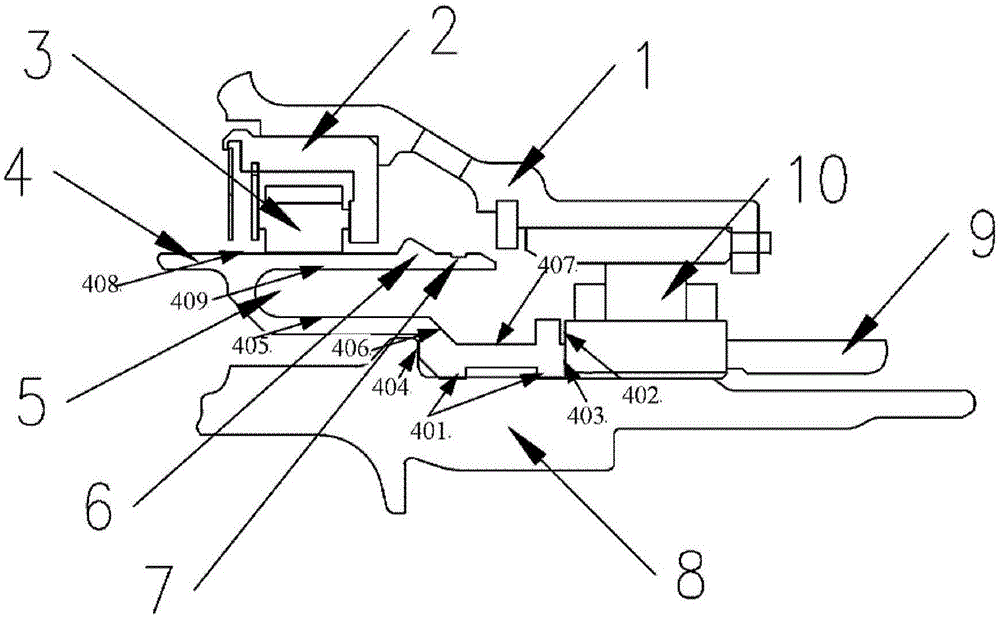
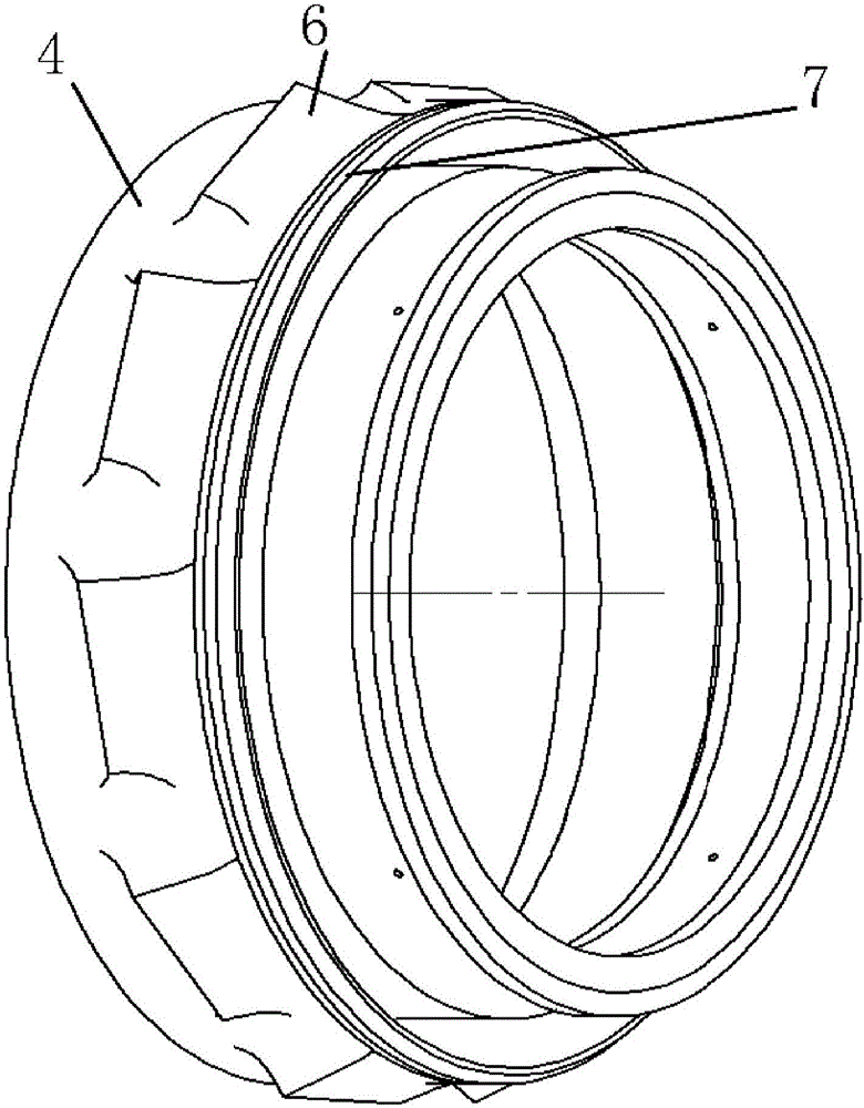
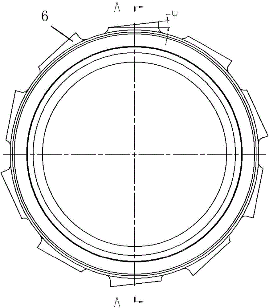
[0029] The invention discloses a graphite ring runway sealing structure used for sealing a bearing cavity, which can be applied in the fields of ground gas turbines, aeroengines and the like. On the runway with a graphite ring for sealing the bearing cavity, an oil cut-off groove and an oil thrower are designed on the side of the working face of the runway (near the side of the bearing cavity). This graphite ring runway pre-seal structure uses the oil cut-off groove to avoid the accumulation of lubricating oil in the bearing cavity, and at the same time uses the oil thrower next to the oil cut-off groove to further throw the lubricating oil droplets that may flow into the sealing surface of the graphite ring back to the bearing through the ac...


PUM


Abstract

The invention discloses a graphite ring runway sealing structure for sealing a bearing cavity, and the structure can be applied to the field of ground combustion gas turbines, aero-engines and the like. The bearing cavity is sealed on a graphite ring runway; an oil cut-off slot and / or an oil thrower is designed at a position, close to the bearing cavity, on the front side of the working surface of the runway. By the use of the oil cut-off slot, the graphite ring runway pre-sealing structure avoids accumulation of lubricating oil in the bearing cavity; meanwhile, the oil thrower beside the oil cut-off slot is used for further throwing the lubricating oil possibly flowing into the sealed surface of a graphite ring back into the bearing cavity under the action of centrifugal force.

Description

technical field [0001] The invention relates to a sealing structure for high-speed rotating bearing cavities in the fields of gas turbines, aeroengines and the like. Background technique [0002] In the fields of gas turbines, aero engines, etc., the high-pressure shaft or low-pressure shaft rotating at high speed transmits power inside the engine or outputs power to the outside. In order to ensure the normal operation of the engine, it is necessary to provide support for the high-speed rotating shaft by arranging bearings. The bearing rotates at a high speed with the rotating shaft, and the lubricating oil with a certain pressure is provided to it through the lubricating oil system to ensure lubrication and cooling, which is an indispensable link to ensure the reliable operation of the bearing. The bearing cavity is an indispensable part of the lubricating oil system. Its important function is to collect the lubricating oil splashed by the bearing and the volatilized oil m...

Claims


Application Information

Patent Timeline
Patent Type & Authority Applications(China)
IPC IPC(8): F02C7/28F02C7/06
CPCF02C7/06F02C7/28
Inventor 杜强刘军王沛柳光杨晓洁朱俊强
Owner INST OF ENGINEERING THERMOPHYSICS - CHINESE ACAD OF SCI
Learn More