A hydraulic transformer with a swinging swash plate and a rotating distribution plate

A technology of hydraulic transformer and distribution plate, applied in the field of hydraulic transformer, can solve the problems of large coupling degree of pressure and flow control, increase the difficulty of system control, poor flow adjustment ability, etc., so as to reduce the instantaneous output flow pulsation and improve the operation stability. , The effect of preventing the speed from changing too much

Active Publication Date: 2017-10-24
BENGBU KUNPENG FOOD & BEVERAGE
View PDF1 Cites 0 Cited by
  • Summary
  • Abstract
  • Description
  • Claims
  • Application Information

AI Technical Summary

Problems solved by technology

The uniform arrangement of three waist-shaped grooves on the distribution plate is beneficial to reduce the volume of the transformer, but there are several technical problems: 1) Since the distribution window is less than 120°, the flow pulsation is large; 2) Depending on the speed of the plunger cylinder 3) Due to the poor stability of the plunger cylinder when the rotation speed is very low, the components work unstable in small flow conditions; 4) The coupling degree of pressure and flow control is large, which increases the system control difficulty

Method used


Image

  • A hydraulic transformer with a swinging swash plate and a rotating distribution plate
  • A hydraulic transformer with a swinging swash plate and a rotating distribution plate
  • A hydraulic transformer with a swinging swash plate and a rotating distribution plate

Examples


Embodiment Construction

[0018] The present invention will be described in further detail below in conjunction with the accompanying drawings and embodiments.

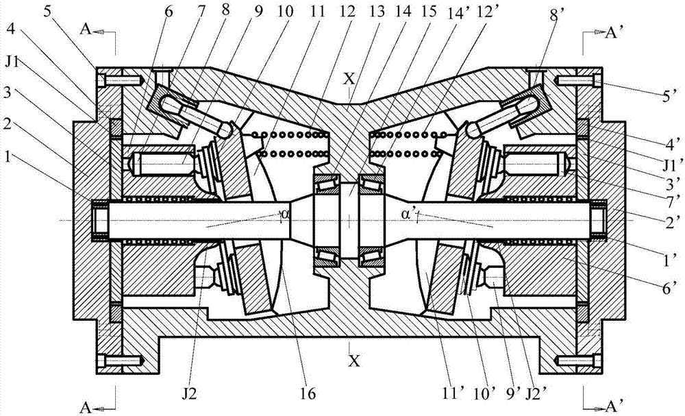
[0019] Such as figure 1 As shown, the left housing 2, the right housing 2' and the middle housing 13 form a closed cavity of the hydraulic transformer; 2 and the bearing cavity of the right housing 2', the middle part of the rotating shaft 15 is installed in the left and right concave cavity of the middle housing 13 through the left and right second bearings 14 and 14' respectively, and the rotating shaft 15 passes through the left and right respectively The second right spline J2, J2' is connected with the left and right plunger cylinders 6, 6', and the left and right plunger cylinders 6, 6' are respectively connected with the left and right plungers 9, 9' to form 9 left plungers Cavities 8 and 9 right plunger chambers 8', the axes of the rotating shaft 15 intersect the axes of the left and right plunger cylinders 6 and 6' at acute angles α ...


PUM


Abstract

The invention discloses a hydraulic transformer with swinging tilting trays and rotating thrust plates, and belongs to the technical field of hydraulic parts. The hydraulic transformer is characterized in that a first unit and a second unit which are located on the left side and the right side of the transformer respectively have the same structure; the first unit is taken as an example, the left thrust plate, a left plunger cylinder and the left tilting tray are sequentially arranged on the left section of a rotating shaft in a sleeving mode from left to right, a left swinging motor rotor is connected with the left thrust plate through a first left spline, the left tilting tray is attached to a middle shell through a left rotating pair, the left side and the right side of the upper end of the left tilting tray are connected with the middle shell through a left tilting tray pushing cylinder and a left reset spring respectively, a first oil hole and a second oil hole of a left shell are communicated with a left plunger cavity through a first waist-shaped groove and a second waist-shaped groove of the left thrust plate respectively, and a first oil hole and a second oil hole of a right shell are communicated with a right plunger cavity through a first waist-shaped groove and a second waist-shaped groove of the second thrust plate respectively. The hydraulic transformer has the advantages of achieving the high transformer ratio, the high pressure and flow response speed and the few pressure-flow coupling influences and eliminating the low-speed stability problem.

Description

technical field [0001] The invention belongs to the technical field of hydraulic parts, and in particular relates to a hydraulic transformer with a swing swash plate and a rotating distribution plate. Background technique [0002] The constant pressure network secondary regulation technology is a very important energy-saving solution in the field of hydraulic transmission today. The hydraulic transformer is the core component of the secondary regulation technology of the constant voltage network. Innas company applied for the invention patent of WO9731185A1. In this patent, the distribution plate of the hydraulic transformer is evenly arranged with three waist-shaped grooves, which are respectively connected with the constant voltage source, the load and the low voltage source. The uniform arrangement of three waist-shaped grooves on the distribution plate is beneficial to reduce the volume of the transformer, but there are several technical problems: 1) Since the distribut...

Claims


Application Information

Patent Timeline
Patent Type & Authority Patents(China)
IPC IPC(8): F15B3/00
CPCF15B3/00
Inventor 仉志强宋建丽李永堂刘志奇贾跃虎
Owner BENGBU KUNPENG FOOD & BEVERAGE
Why Eureka
Try Eureka