Rotary booster energy-absorbing cylinder fixing device

The technology of a fixing device and an energy-absorbing cylinder is applied in the field of machinery, which can solve the problems of large workload and low work efficiency, and achieve the effects of firm fixing, simple structure and preventing forward movement.

Active Publication Date: 2018-08-24
HUNAN UNIV
View PDF7 Cites 0 Cited by
  • Summary
  • Abstract
  • Description
  • Claims
  • Application Information

AI Technical Summary

Problems solved by technology

The invention solves the shortcomings of the traditional welding and fixing energy-absorbing cylinder, which is limited by the site and equipment, low work efficiency and heavy workload, and proposes a simple energy-absorbing cylinder fixing device, which has a simple structure, strong working reliability and repeatability Utilization, especially suitable for the fixing of energy-absorbing cylinders of various specifications

Method used


Image

  • Rotary booster energy-absorbing cylinder fixing device
  • Rotary booster energy-absorbing cylinder fixing device

Examples


Embodiment 1

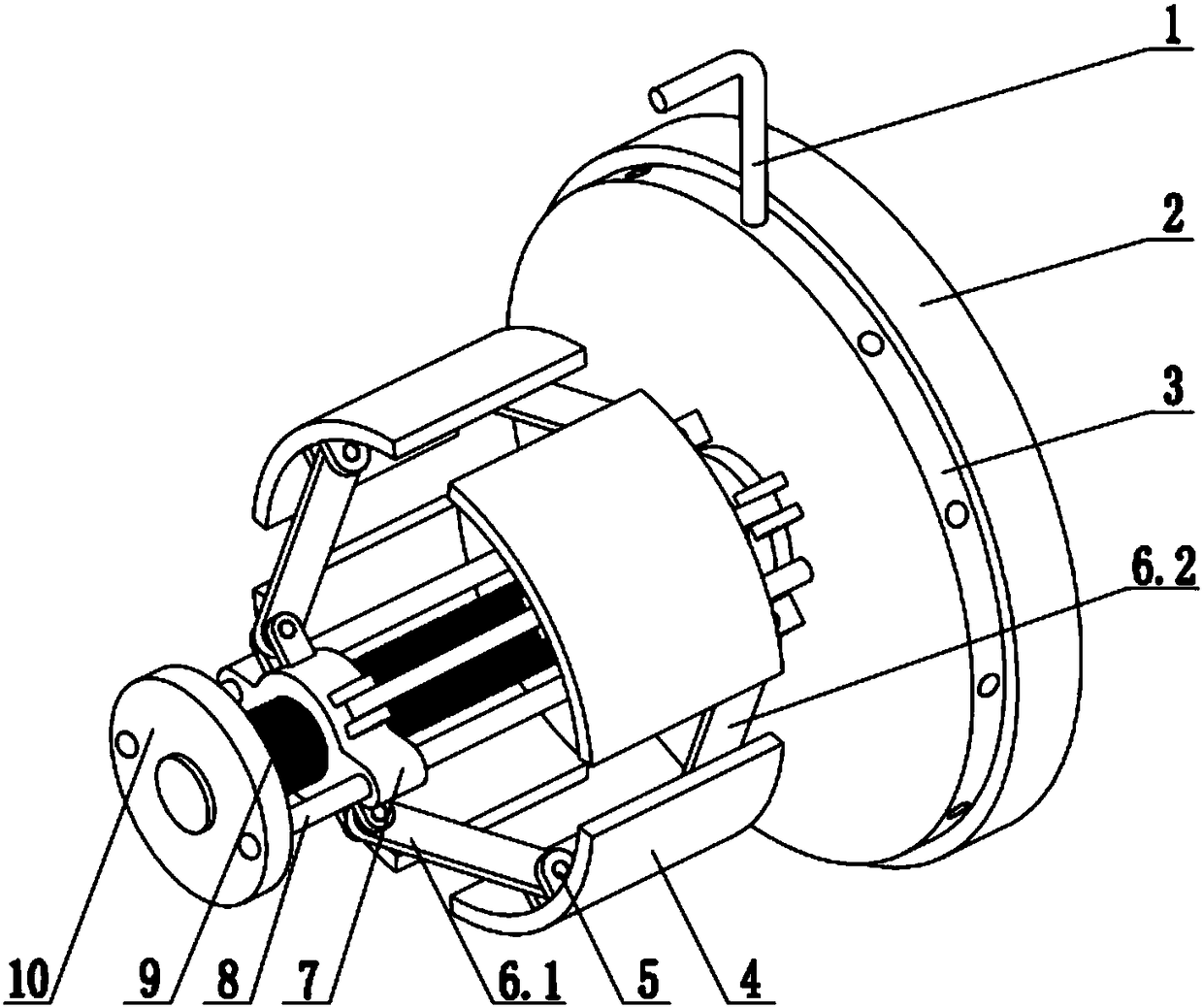
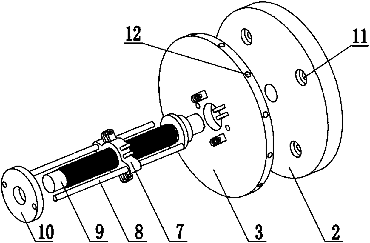
[0021] Such as figure 1 and figure 2 The shown rotating power-boosting type energy-absorbing cylinder fixing device mainly includes a rotating rod 1, a fixed chassis 2, a rotating disk 3, a tension piece 4, a rotating pin 5, a first connecting rod 6.1, and a second connecting rod 6.2 , sliding block 7, guide rod 8, screw mandrel shaft 9, rotating piece 10.

[0022] The fixed chassis 2 is fixed on the front end of the trolley through screw holes 11 or directly welded to the front end of the trolley. Welding together, the rotating disk 3 can rotate between the screw shaft 9 and the fixed chassis 2 at this time, the rotating piece 10 is sleeved on the screw shaft 9, the guide rod 8 passes through the two holes of the sliding block 7, and inserts In the two holes corresponding to the rotating disk 3, they are connected by welding. The other end of the guide rod 8 is inserted in the hole of the rotating piece 10 and connected by welding. The rotating piece 10 and the sliding bl...


PUM


Abstract

The invention discloses a rotating force-increasing energy absorption barrel fixing device. The rotating force-increasing energy absorption barrel fixing device mainly comprises a rotary rod 1, a fixed base plate 2, a rotary disk 3, tensioning sheets 4, rotary pins 5, first connecting rods 6.1, second connecting rods 6.2, sliding blocks 7, guide rods 8, a lead screw shaft 9 and a rotary sheet 10. One end of the lead screw shaft 9 is fixedly connected with the fixed base plate 2. The rotary disk 3 is rotationally connected with the lead screw shaft 9. The rotary disk 3 rotates to drive the guide rods 8 and the rotary sheet 10 to rotate so as to drive the sliding blocks 7 to rotate and slide along the lead screw shaft 9. The tensioning sheets 4 are pushed to do radial motion through the first connecting rods 6.1 and the second connecting rods 6.2, and then an energy absorption barrel is tensioned. By adopting the rotating force-increasing energy absorption barrel fixing device, the problems of site and equipment constrains, low working efficiency and large workload caused by traditional energy absorption barrel welding and fixing methods are solved. The simple energy absorption barrel fixing device provided by the invention is simple in structure, high in work reliability, capable of being utilized repeatedly and particularly suitable for fixation of various energy absorption barrels of different specifications.

Description

technical field [0001] The invention belongs to the field of machinery, and in particular relates to a fixing device for a rotating booster type energy-absorbing cylinder. Background technique [0002] At present, in the crash test of the trolley, the energy-absorbing cylinder is mainly fixed by welding, but the welding work efficiency is low, and after the collision is completed, the energy-absorbing cylinder needs to be cut to remove it, which cannot be reused. Due to the need for welding equipment, the use of traditional welding methods will be greatly affected by the site and equipment. [0003] Patent 201510545865.0 discloses an energy-absorbing tube fixing device to solve the above problems, but there are still some defects, such as 1. When the energy-absorbing tube is placed on the device, a hexagonal wrench needs to be inserted from the front end of the energy-absorbing tube for alignment The hexagonal hole, because sometimes the energy-absorbing cylinder may be rel...

Claims


Application Information

Patent Timeline
Patent Type & Authority Patents(China)
IPC IPC(8): F16B2/04
CPCF16B2/04
Inventor 曹立波石海兵
Owner HUNAN UNIV
Why Eureka
Try Eureka