Gas turbine combustor

A gas turbine and burner technology, applied in the direction of gas turbine devices, combustion chambers, combustion methods, etc., can solve the problems of increased pressure loss, complex support methods, etc., and achieve the effects of easy bending, NOx reduction, and more disturbance

Active Publication Date: 2017-01-04
MITSUBISHI POWER LTD
View PDF8 Cites 12 Cited by
  • Summary
  • Abstract
  • Description
  • Claims
  • Application Information

AI Technical Summary

Problems solved by technology

Therefore, there are problems that the support method becomes complicated, and the pressure loss increases due to the insertion of the structure
[0020] In the technology described in Patent Document 2, a method of increasing the flow rate on the inner peripheral side by a flow rate adjustment mechanism, and a method of suppressing separation of the flow at the inversion part by disturbing the entire flow path are proposed. However, in adjusting the flow rate, When the flow is disturbed, it is necessary to apply resistance to the flow, so there is a problem that the pressure loss increases due to the flow rate adjustment mechanism

Method used


Image

  • Gas turbine combustor
  • Gas turbine combustor
  • Gas turbine combustor

Examples


Embodiment 1

[0041] use figure 1 ~ FIG. 6, the gas turbine combustor according to the first embodiment of the present invention will be described.

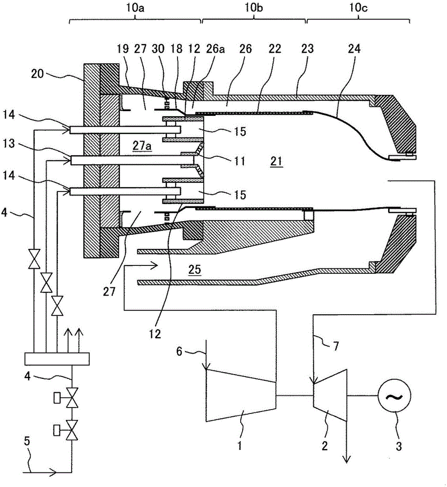
[0042] figure 1 A sectional view showing a gas turbine combustor 10 according to a first embodiment of the present invention.

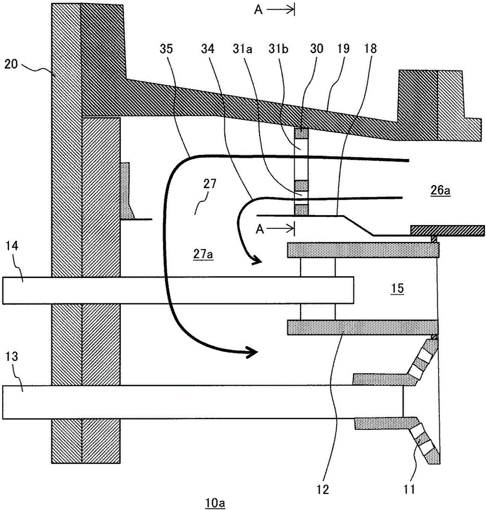
[0043] figure 2 will be figure 1 The shown partial cross-sectional view is enlarged and shows a part of the air flow path of the gas turbine combustor 10 according to the first embodiment of the present invention.

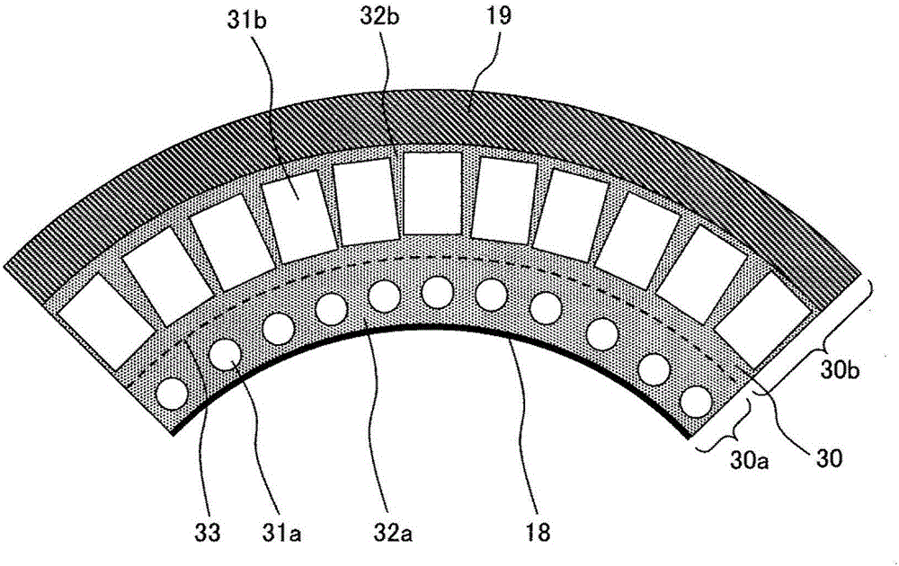
[0044] image 3 Indicates the shape of the obstacle of the gas turbine combustor according to the first embodiment of the present invention provided in the air flow path, figure 2 A view from direction A-A.

[0045] for figure 1 The shown gas turbine generator equipped with the gas turbine combustor 10 according to the first embodiment of the present invention constitutes the gas turbine generator by the following parts: a compressor 1 which acquires combustion air 6 and compresses it; a gas turbi...

Embodiment 2

[0114] use Figure 4 and Figure 5 A gas turbine combustor 10 according to a second embodiment of the present invention will be described.

[0115] Figure 4 It is an enlarged cross-sectional view showing a part of the air flow path 26 of the gas turbine combustor 10 according to the second embodiment of the present invention.

[0116] Figure 5 It shows the shape of the obstacle 50 provided in the air flow path 26a of the gas turbine combustor 10 according to the second embodiment of the present invention. Figure 4 A view from direction A-A.

[0117] Figure 4 and Figure 5 The shown basic structure of the gas turbine combustor 10 according to the second embodiment of the present invention is substantially the same as that of the gas turbine combustor 10 according to the first embodiment, and therefore description thereof will be omitted.

[0118] In the gas turbine combustor 10 of the second embodiment of the present invention, the difference from the gas turbine com...


PUM


Abstract

The present invention provides a gas turbine combustor in which the pressure loss and the flow deviation in the flow path reversing portion of the gas turbine combustor are reduced to uniformly mix a fuel with air to reduce NOx. The gas turbine combustor is characterized in that a combustor head portion has an inner casing that differentiates the inner periphery from the outer periphery and supplies air, an outer casing that surrounds the inner casing, and an airflow path provided between the inner casing and the outer casing; an opening portion that introduces the air flowing down the airflow path to an inner periphery side of the inner casing of the combustor is provided in the inner casing; a flow path deflection part deflecting the air flow at the opening portion is formed on the inner periphery side of the inner casing; an obstacle that impedes flow of the air is provided in the airflow path on an upstream side of the opening portion, and the obstacle is formed by a perforated plate comprising a plurality of holes that flow a stream of the air, and the obstacle is configured such that an opening ratio representing a ratio of the area of an opening portion to the area of a shielding portion aside from the hole that shields the flow of the air is low on an inner periphery side of the obstacle and high on an outer periphery side of the obstacle.

Description

technical field [0001] The present invention relates to a gas turbine combustor, and more particularly to a gas turbine combustor having a flow path structure that suppresses bias of air flowing inside the gas turbine combustor to reduce pressure loss. Background technique [0002] For gas turbine combustors, it is desired to reduce nitrogen oxides (NOx) and unburned amounts in combustion gas to obtain high environmental performance, and to reduce pressure loss of air flowing in gas turbine combustors to improve power generation efficiency. [0003] For the reduction of NOx, it is effective to apply a premix combustion method in which fuel and air are premixed before combustion to a gas turbine combustor. Fuel and air are mixed and burned in a lean state with less fuel, thereby lowering the flame temperature and suppressing NOx generated at high temperature. [0004] When this premixed combustion method is used for the gas turbine combustor, it is necessary to distribute th...

Claims


Application Information

Patent Timeline
Patent Type & Authority Applications(China)
IPC IPC(8): F23R3/02F23R3/28
CPCF23R3/02F23R3/28F23R3/26F23R3/286F23R3/343F23R3/10F23R3/08F23R3/16F23R3/42F05D2240/35F02C3/145F05D2220/32F23R3/50F23R3/54
Inventor 冈崎洋文折井明仁宇留野智纪
Owner MITSUBISHI POWER LTD
Why Eureka
Try Eureka