Stereo vision sensor integrates line array camera and area array camera and calibration method
A technology of line scan camera and area scan camera, applied in instruments, measuring devices, optical devices, etc., can solve problems such as identification errors
- Summary
- Abstract
- Description
- Claims
- Application Information
AI Technical Summary
Problems solved by technology
Method used
Image

Examples
Embodiment Construction
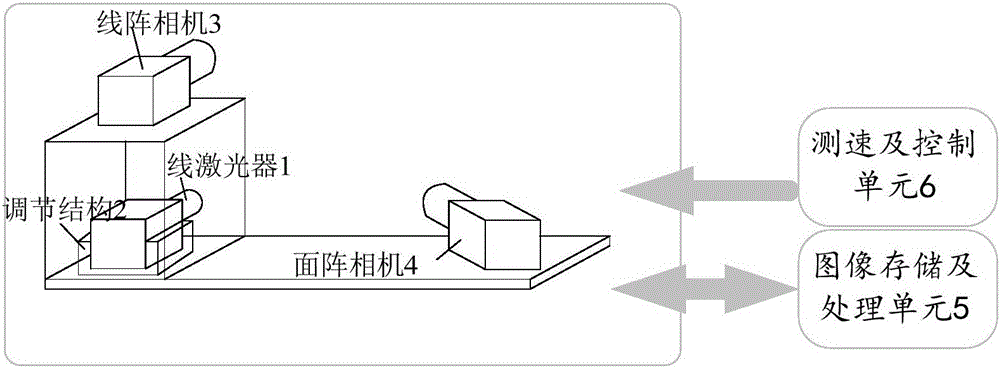
[0048] figure 1 It is a schematic structural diagram of the stereo vision sensor in the embodiment of the present invention. Such as figure 1 As shown, in the stereo vision sensor, the line laser 1 is installed on a three-degree-of-freedom adjustment mechanism 2, and the adjustment mechanism 2 is placed under the line array camera 3, and the light plane projected by the laser 1 is aligned with the line array camera through the adjustment mechanism 2. The optical center of 3 coincides with the plane formed by the line array CCD, ensuring that the line laser 1 provides good illumination for the line array camera 3 . The area camera 4 is placed on one side of the line camera 3 . The area camera 4 and the line camera 3 constitute a stereo vision sensor. The line scan camera 3 and the area scan camera 4 are connected to an image storage and processing unit 5 through an image acquisition device. The speed measurement and control unit 6 is used to measure the speed of the object,...
PUM
 Abstract
Description
Claims
Application Information