Air pressure environment stabilizing structure and inertial measuring unit of unmanned aerial vehicle

An air pressure measuring device, a technology of unmanned aerial vehicle, which is applied in the direction of measuring device, measuring fluid pressure, and navigating through speed/acceleration measurement, etc., can solve problems such as affecting the working of the air pressure measuring device, interference of wind speed, and measurement fluctuation of the air pressure measuring device, etc. Achieve the effect of avoiding local high-speed and low-pressure environment, stabilizing the working environment, and avoiding excessive wind speed

Active Publication Date: 2017-01-04
丰翼科技(深圳)有限公司
View PDF8 Cites 3 Cited by
  • Summary
  • Abstract
  • Description
  • Claims
  • Application Information

AI Technical Summary

Problems solved by technology

When the air pressure measurement device is used on the ground because the external environment is stable, there is no problem; however, during the use of the flight environment, due to factors such as high maneuvering speed, large altitude drop, and large wind speed interference in the flight environment, it is easy to cause the air pressure measurement devic

Method used


Image

  • Air pressure environment stabilizing structure and inertial measuring unit of unmanned aerial vehicle
  • Air pressure environment stabilizing structure and inertial measuring unit of unmanned aerial vehicle

Examples


Embodiment Construction

[0016] The application will be further described in detail below in conjunction with the accompanying drawings and embodiments. It should be understood that the specific embodiments described here are only used to explain related inventions, rather than to limit the invention. It should also be noted that, for ease of description, only parts related to the invention are shown in the drawings.

[0017] It should be noted that, in the case of no conflict, the embodiments in the present application and the features in the embodiments can be combined with each other. The present application will be described in detail below with reference to the accompanying drawings and embodiments.

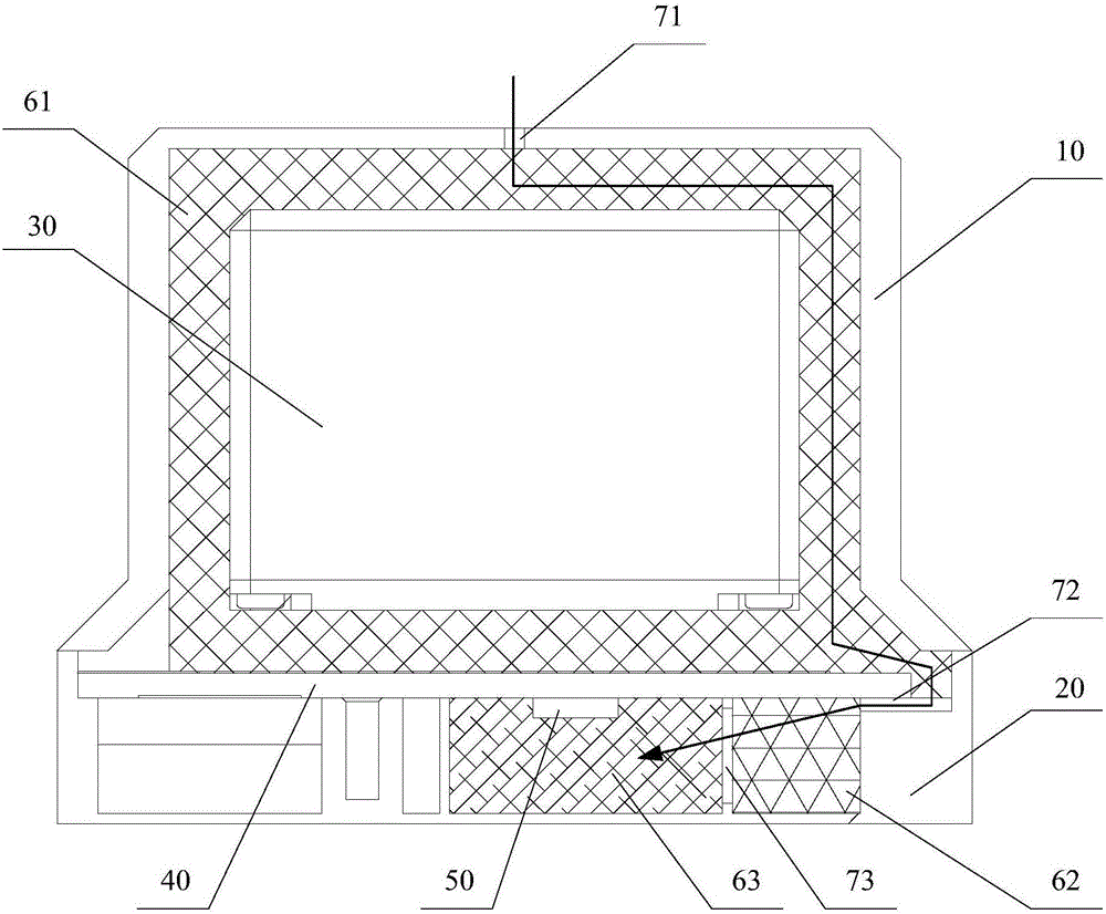
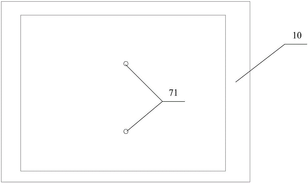
[0018] figure 1 It is a structural schematic diagram of the stable air pressure environment structure of the drone in an embodiment of the present invention.

[0019] Such as figure 1 As shown, in this embodiment, the UAV stable air pressure environment structure provided by the present inventio...


PUM

PropertyMeasurementUnit
Diameteraaaaaaaaaa
Diameteraaaaaaaaaa

Abstract

The invention discloses an air pressure environment stabilizing structure and an inertial measuring unit of an unmanned aerial vehicle. The air pressure environment stabilizing structure comprises a shell and an air pressure measuring device fixed into the shell; a first air pore passage is formed in the shell; at least two layers of buffer media are arranged between the first air pore passage and the air pressure measuring device; a gap for air to pass is formed in each buffer medium; an air pore passage is formed between every two adjacent buffer media; the air pore passages together with the buffer media form an air passage for air outside the shell to reach the air pressure measuring device. According to the air pressure environment stabilizing structure and the inertial measuring unit of the unmanned aerial vehicle, provided by the invention, according to the principle of fluid mechanics, through arrangement of a plurality of the air pore passages with relatively small sections and the buffer media with relatively small gaps, the air passage for the air outside the shell to reach the air pressure measuring device is formed, so that the speed of the air reaching the air pressure measuring device cannot be too high and a local high-speed and low-pressure environment caused by single pore passage connection is avoided, and thus a stable working environment is provided for the air pressure measuring device of the unmanned aerial vehicle.

Description

technical field [0001] The present application relates to the technical field of unmanned aerial vehicles, in particular to an unmanned aerial vehicle stable air pressure environment structure and an inertial measurement unit. Background technique [0002] Inside the drone is a device for measuring air pressure, usually in an inertial measurement unit. When the air pressure measurement device is used on the ground because the external environment is stable, there is no problem; however, during the use of the flight environment, due to factors such as high maneuvering speed, large altitude drop, and large wind speed interference in the flight environment, it is easy to cause the air pressure measurement device to fail. The measurement fluctuates and even seriously deviates. [0003] At the same time, for rotary-wing UAVs, the propeller will affect the surrounding air pressure environment; for fixed-wing UAVs, complex air pressure environments such as turbulence will be forme...

Claims


Application Information

Patent Timeline
IPC IPC(8): G01L19/06G01C21/16
CPCG01C21/16G01L19/0609
Inventor 雷鹏涛
Owner 丰翼科技(深圳)有限公司
Why Eureka
Try Eureka