Preparation method for aspherical vision correction lens with controllable peripheral defocus

A technology of vision correction and aspheric surface, which is applied in the field of preparation of aspheric vision correction lens, and can solve problems such as halo formation, multi-layer structure interference in the optical zone, mutual interference, etc.

Active Publication Date: 2017-01-04
EYEBRIGHT MEDICAL TECH BEIJING
View PDF3 Cites 29 Cited by
  • Summary
  • Abstract
  • Description
  • Claims
  • Application Information

AI Technical Summary

Problems solved by technology

However, there are two problems in this way of realizing peripheral defocus control. First, because the lens only contains two kinds of radians, the optical imaging process is similar to a partitioned multi-focal lens, and each focal point interferes with each other, forming a halo phenomenon; second, because The radius of curvature between each arc segment is different, and the connection between the rings will cause a lot of stray light. Therefore, the biggest problem of this kind of lens is that the imaging is interfered by the multi-layer structure of the optical zone, and the visual quality is poor.
[0010] So far, the technology that uses peripheral defocus to control the growth of myopia faces two major problems. One is the lack of a clear and quantifiable implementation of peripheral defocus control; the other is the lack of effective and controllable treatment products.

Method used


Image

  • Preparation method for aspherical vision correction lens with controllable peripheral defocus
  • Preparation method for aspherical vision correction lens with controllable peripheral defocus
  • Preparation method for aspherical vision correction lens with controllable peripheral defocus

Examples


preparation example Construction

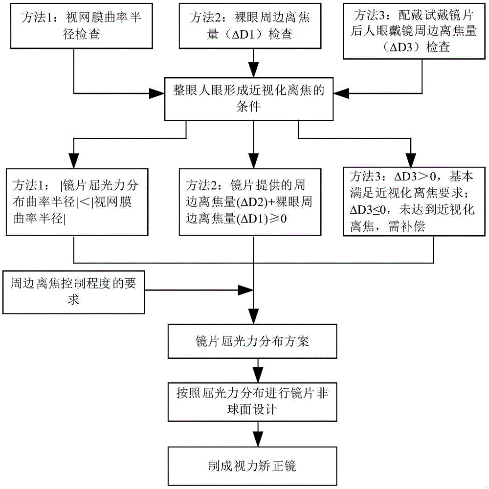
[0060] Such as figure 2 Shown, the preparation method of the peripheral defocus controllable aspheric vision correction lens of the present invention, it it comprises the steps:

[0061] (1) By examining the shape of the retina of the human eye or the peripheral defocus of the naked eye of the human eye or the defocus of the peripheral defocus of the human eye wearing glasses, calculate and judge the conditions required for the formation of myopia defocus of the human eye;

[0062] (2) According to the conditions obtained by myopia defocusing, form the distribution scheme of the refractive power of the vision correction lens as the aperture changes;

[0063] (3) According to the refractive power distribution plan of the vision correction lens obtained above, the vision correction lens is made into a vision correction lens, and after the refractive power of the vision correction lens is added to the human eye, the refractive power distribution of the whole eye refractive power...

Embodiment 1

[0093] In this embodiment, the vision correction glasses are vision correction glasses worn outside the eyes (such as frame glasses).

[0094] Such as Image 6 As shown, in this embodiment, in addition to the existing fitting methods of RGP and frame glasses, it also includes the preparation method of the peripheral defocus controllable aspheric vision correction lens of the present invention, which includes the following steps:

[0095] (1) By examining the shape of the retina of the human eye or the peripheral defocus of the naked eye of the human eye or the defocus of the peripheral defocus of the human eye wearing glasses, calculate and judge the conditions required for the formation of myopia defocus of the human eye;

[0096] (2) According to the conditions obtained by myopia defocusing, form the distribution scheme of the refractive power of the vision correction lens as the aperture changes;

[0097] (3) According to the refractive power distribution plan of the visio...

Embodiment 2

[0100] In this embodiment, the vision correction lens is an orthokeratology lens.

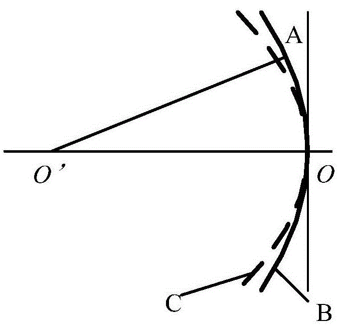
[0101] Such as Figure 7 As shown, in this embodiment, the basic design method of the orthokeratology lens is the same as the existing method, but the surface shape of the base arc area is determined by the curvature of the retina, and the refractive power distribution state that the human retina needs to achieve is calculated according to the curvature of the retina. Ensure that the refractive power of the human eye tends to become larger as the aperture becomes larger than the curvature of the retina, forming hyperopic peripheral defocus, thereby preventing the extension of the visual axis of the human eye and controlling the growth of myopia. According to the distribution of the refractive power of the human eye, the surface shape of the inner surface (base arc area) of the orthokeratology lens is designed, because the principle of the orthokeratology lens is that after the human eye wears t...


PUM


Abstract

The invention relates to a preparation method for an aspherical vision correction lens with controllable peripheral defocus. The preparation method comprises the following steps: (1) through the checking of human eye retina shape or human naked eye peripheral defocusing amount or human eye glasses-wearing peripheral defocusing amount, calculating and judging the conditions needed by forming myopization defocus of the human eye; (2) according to the conditions obtained by the myopization defocus, forming a distribution solution of refractive power of the vision correction lens changed along with the pore diameter; (3) according to the distribution solution of the refractive power of the vision correction lens, making the vision correction lens, so the refractive power distribution in the peripheral area of the whole eye refractive power formed on the retina is greater than that in the center area after the refractive power of the vision correction lens is attached to the human eye, and forming the myopization defocus before falling on the retina; using an aspheric surface to control the surface shape and curvature radius of an optic zone of the vision correction lens, so that the vision correction lens is evenly changed in the aperture direction according to the stated refractive power peripheral defocusing amount, the refractive power is increased along with the increase of the aperture, so the degree-controllable myopization defocus is provided to the human eye.

Description

technical field [0001] The invention relates to a preparation method of a vision correction lens, in particular to a preparation method of an aspheric vision correction lens with controllable peripheral defocus. Background technique [0002] Defocus (Defocus, out-of-focus) is the corresponding word of focus. Defocus means that the image plane is not in focus. It is divided into two types: front defocus (before focus) and back defocus (after focus). state. [0003] The main reason for the increase in the degree of myopia is the extension of the axial length of the eye, and the degree increases by 3.00 degrees for every 1mm of extension. The latest medical research confirms that the elongation of the eyeball depends on the retina (such as figure 1 10) peripheral defocus, according to the concept of refractive optics, the focal point falls in front of the retina is called myopic defocus (such as figure 1 30 in the center), those who fall behind the retina are called hyperopi...

Claims


Application Information

Patent Timeline
Patent Type & Authority Applications(China)
IPC IPC(8): G02C7/04
Inventor 王曌解江冰
Owner EYEBRIGHT MEDICAL TECH BEIJING
Why Eureka
Try Eureka