orthokeratology lens

An orthokeratology lens and lens technology, applied in glasses/goggles, optical components, instruments, etc., can solve the problem of inability to control the growth of myopia, the inability of orthokeratology lenses to form peripheral refractive power control, and the different degrees of retinal curvature. And other issues

Active Publication Date: 2020-02-07
EYEBRIGHT MEDICAL TECH BEIJING
View PDF9 Cites 0 Cited by
  • Summary
  • Abstract
  • Description
  • Claims
  • Application Information

AI Technical Summary

Problems solved by technology

[0012] The base arcs of existing orthokeratology lenses are all spherical, and the base arcs of the sphere will shape the front surface of the cornea into a spherical surface, so that the distribution of refractive power provided by the cornea conforms to the characteristics of a spherical surface. The disadvantage is that, for different patients, the retinal The degree of curvature is different. The existing orthokeratology lens shapes the outer surface of the cornea into a spherical shape in the base arc area, and its refractive power distribution only follows the distribution law of the spherical surface. As far as the radius of curvature of the surface is concerned, its refractive power distribution has only one form
For example, for a cornea with a corneal curvature radius of 42.25D after shaping, its refractive power distribution can only be as follows: image 3 In a situation shown in A, when the curvature of the human retina is greater than the curvature of the refractive power distribution formed by the cornea shown in the figure, it will not be possible to form myopic peripheral defocus, and thus cannot achieve the purpose of controlling the growth of myopia
Therefore, orthokeratology lenses with a spherical base curve cannot form a controllable and effective peripheral refractive power control, so only some patients can benefit from the control of myopia growth, and it is impossible to achieve effective control of myopia for every patient

Method used


Image

  • orthokeratology lens
  • orthokeratology lens
  • orthokeratology lens

Examples


Embodiment Construction

[0038] In order to make the technical means, creative features, goals and effects achieved by the present invention easy to understand, the present invention will be further described below in conjunction with specific illustrations.

[0039] Definition of Terms:

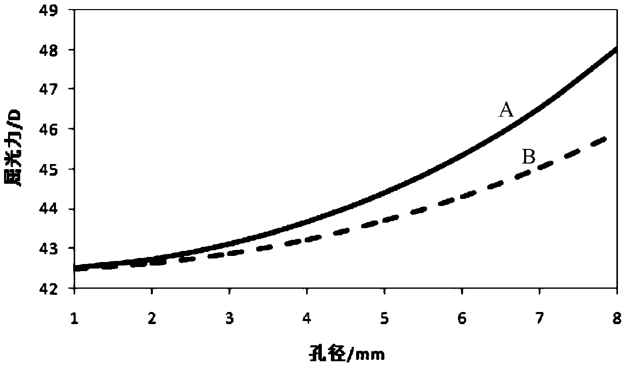
[0040] The term "optical zone" as used in this application refers to the portion located in the central area of ​​the lens that has optical properties so as to be able to perform the main function of adjusting the diopter of the lens.

[0041] The term "radial" as used in this application refers to a linear direction along a radius or diameter from the center of the lens.

[0042] The term "aperture" as used in this application refers to the size of the diameter radial to the surface of the lens.

[0043] The terms used in the present application to express orientation relations such as "anterior" and "posterior" are relative to the distance of the corneal surface of the eye. For example, in the lens of the presen...


PUM


Abstract

The invention aims at disclosing cornea shaping glass. A base curve area of a lens is an aspheric surface, and through the aspheric surface, an absolute value of the equivalent curvature radius of the periphery of the lens base curve area is smaller than that of the curvature radius of the center of the lens base curve area. Compared with the prior art, the cornea shaping glass has the advantages that the surface shape and the curvature radius of the lens are controlled through the aspheric surface, therefore, the absolute value of the equivalent curvature radius of the periphery of the lens base curve area is smaller than that of the curvature radius of the center of the lens base curve area, and the peripheral surface shape is steeper than a spherical surface; by wearing the glass for a night, the front surface of the human cornea is shaped into the shape of the base curve area of the cornea shaping glass, therefore, degree-controllable myopization defocusing is provided for the human eye, the condition that the eye axis is lengthened is prevented, myopia deepening is delayed, and the purpose is achieved.

Description

technical field [0001] The present invention relates to a vision correcting glasses, in particular to an orthokeratology lens whose base arc area is aspherical to control the development of myopia by using peripheral defocusing. Background technique [0002] Defocus (Defocus, out-of-focus) is the corresponding word of focus. Defocus means that the image plane is not in focus. It is divided into two types: front defocus (before focus) and back defocus (after focus). state. [0003] The main reason for the increase in the degree of myopia is the extension of the axial length of the eye, and the degree increases by 3.00 degrees for every 1mm of extension. The latest medical research confirms that the elongation of the eyeball depends on the retina (such as figure 1 10) peripheral defocus, according to the concept of refractive optics, the focal point falls in front of the retina is called myopic defocus (such as figure 1 30 in the center), those who fall behind the retina ar...

Claims


Application Information

Patent Timeline
Patent Type & Authority Patents(China)
IPC IPC(8): G02C7/04
Inventor 王曌解江冰
Owner EYEBRIGHT MEDICAL TECH BEIJING
Why Eureka
Try Eureka