Light emitting device, light emitting control method and projection device

A light-emitting device and light-emitting control technology, applied in the field of projection, can solve the problems of ineffective display of pixel colors, unfavorable energy and cost saving, and ineffective display of pixels, etc.

Active Publication Date: 2017-01-04
APPOTRONICS CORP LTD
View PDF17 Cites 45 Cited by
  • Summary
  • Abstract
  • Description
  • Claims
  • Application Information

AI Technical Summary

Problems solved by technology

[0003] However, in the prior art, if only red fluorescent light is used as the primary color light, then for a certain frame of image, the color of pixels whose color coordinates fall outside the GBR cannot be effectively displayed
[0004] Similarly, if only the red laser is used as the red primary color light, for a certain frame of image, the color of the pixels whose color coordinates fall outside GBR’ cannot be effectively displayed
[0005] In the case of using the mixed light of red fluorescent light and red laser light as the red primary color light, for some images, since all pixels in the picture are in GBR, that is, there is no need to use the "RBR" area, so that the corresponding red fluorescent light and red light are turned on at the same time The laser light source will cause a lot of waste of electric energy, which is not conducive to saving energy and expenses, and seriously affects the practicability of projection equipment products

Method used


Image

  • Light emitting device, light emitting control method and projection device
  • Light emitting device, light emitting control method and projection device
  • Light emitting device, light emitting control method and projection device

Examples


Embodiment 1

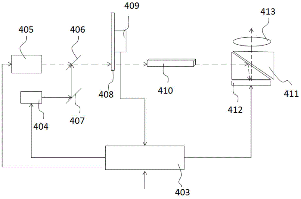
[0054] like image 3 Shown is a schematic structural view of the projection device of this embodiment, the projection device includes a main light source 405, a spectral filter 406, a color wheel 408, a driving device 409, a shaping lens 410, a prism device 411, and a spatial light modulator (Spatial Light Modulators , SLM) 412, exit lens 413, controller 403, first compensating light source 404, reflector 407. Wherein, the main light source 405, the spectral filter 406, the first compensation light source 404, the reflector 407, the color wheel 408, the driving device 409, and the controller 403 together constitute the light emitting device of the projection device.

[0055] The combination of main light source 405, spectroscopic filter 406, color wheel 408, driving device 409, and shaping lens 410 is used to generate a periodic and time-sequential colored light sequence, and project the colored light sequence outward along the designed optical path, passing through the shapin...

Embodiment 2

[0083] Such as Figure 9 As shown, this embodiment provides a light emitting device of a projection device, including a main light source 405 , a first compensation light source 404 , a spectral filter 406 , a reflector 407 , and a color wheel 408 . The main light source 405 , the first compensation light source 404 , and the color wheel 408 are all controlled by the controller 403 . The color wheel 408 absorbs the excitation light 100 and generates a light sequence formed by the three primary colors of light 101 , 102 , and 103 , that is, the first light.

[0084] The difference between this embodiment and Embodiment 1 is that the first compensation light source 404 produces the compensation excitation light 201, and the color wheel 408 absorbs the compensation excitation light 201 to generate the first compensation light 200 (in this case, the first compensation light 200 and the three primary colors of the first light are fluorescence). Other technical features of this em...

Embodiment 3

[0086] Such as Figure 10 As shown, this embodiment provides a light emitting device of a projection device, including a main light source 405 , a first compensation light source 404 , a spectral filter 406 , a reflector 407 , and a color wheel 408 . The main light source 405 , the first compensation light source 404 , and the color wheel 408 are all controlled by the controller 403 . The color wheel 408 absorbs the excitation light 100 and generates a light sequence formed by the three primary colors of light 101 , 102 , and 103 .

[0087] The difference between this embodiment and Embodiment 1 is that a spectroscopic filter 4060 and a diffuser 4070 are arranged on the optical path after the color wheel 408, and the diffuser 4070, on the one hand, performs Reflection, on the other hand, also plays a role in decoherence. The first compensation light 200 in this embodiment does not pass through the color wheel 408 but merges with the light sequence thereafter. Other technica...


PUM


Abstract

The invention discloses a light emitting device, a light emitting control method and a projection device. The light emitting device comprises a main light source; the light emitting device emits three kinds of primary light through turning on a main light source, wherein a color gamut formed on a coordinate graph is a first color gamut; the light emitting device also comprises a compensation light source for emitting compensation light; the compensation light is used for compensating at least one kind of light in the three kinds of primary light; if color coordinators of all pixels of a projection image of a current frame are all in the first color gamut area, the main light source is controlled to be turned on to enable the light emitting device to emit three kinds of primary light and the compensation light source is controlled not to emit light; if pixels, the color coordinates of which are beyond the first color gamut, exist, the main light source is controlled to be turned on and the compensation light source is controlled to be turned on to make the light emitting device emit compensation light; when the color coordinates of all pixels are all in the first color gamut, the compensation light source is not turned on, and when some pixels are located beyond the first color gamut area, the first compensation light source is turned on, so that an energy saving effect is achieved.

Description

technical field [0001] The present invention relates to the field of projection technology, in particular to a light emitting device, a light emitting control method, and projection equipment. Background technique [0002] like figure 1 Shown is a schematic diagram of the color gamut results before and after the compensation light source is used by the projection device in the prior art, as shown in figure 2 Shown is a comparison diagram of the color gamut before and after the compensation light source is used for the projection device in the prior art, figure 2 is for illustrative purposes figure 1 And the schematic diagram made, figure 1 and figure 2 The compensation light used by the projection equipment is red laser. combine figure 1 and figure 2 It can be seen that in the prior art, when the red light among the three primary colors required by the projection device is fluorescent (for example, a color light generating device is used to generate the three prim...

Claims


Application Information

Patent Timeline
Patent Type & Authority Applications(China)
IPC IPC(8): G03B21/20H05B37/02H05B45/20
CPCG03B21/20
Inventor 李屹王则钦郭祖强
Owner APPOTRONICS CORP LTD
Why Eureka
Try Eureka