Relay push card structure and relay containing push card

A technology for pushing cards and relays, applied in the direction of relays, electromagnetic relays, detailed information of electromagnetic relays, etc., can solve problems such as poor practicability, poor stability and reliability, and affect the stability and reliability of relays, so as to achieve reliable assembly and improve movement The effect of precision, stability and reliable operation

Active Publication Date: 2017-01-04
SICHUAN HONGFA ELECTROACOUSTIC
View PDF8 Cites 7 Cited by
  • Summary
  • Abstract
  • Description
  • Claims
  • Application Information

AI Technical Summary

Problems solved by technology

[0005] 1. In the plug-in assembly structure of the push card, in order to ensure the stability of the assembly of the push card with the armature and the moving reed, the connection between the armature connection part of the push card and the surface of the armature, the connection part of the moving spring of the push card and the moving spring Large surface contact is formed between the surfaces of the slices. Due to the seesaw action effect of the armature, the push card will inevitably produce a non-linear (ie arc) motion track during the force transmission process, which affects the motion accuracy of the push card. Inevitably, it will affect the stability and reliability of the relay operation, which is not conducive to the extension of its service life;
[0006] 2. The plug-in assembly structure between the push card and the armature, and between the push card and the moving reed makes it impossible to effectively realize the automation of the push card assembly during the production process of the relay, and it needs to be done manually. It is conducive to the improvement of the stability and reliability of the finished relay, but also reduces the production efficiency of the relay, increases the production cost, and has poor practicability;
[0007] 3. The plug-in assembly structure between the push card and the armature, and between the push card and the moving reed, no matter during production and assembly or when the finished product is in service, it is easy to break due to friction and scratches at their plug-in assembly parts. Generate lint that affects the electrical performance, which is not conducive to the improvement and protection of the stability and reliability of the relay
[0008] To sum up, due to the structural characteristics of the push card itself, the existing push card relays have the technical problems of low operating efficiency and poor economy in the production process of the applied relays. The technical problems of poor performance and reliability need to be improved and solved urgently

Method used


Image

  • Relay push card structure and relay containing push card
  • Relay push card structure and relay containing push card
  • Relay push card structure and relay containing push card

Examples


Embodiment 1

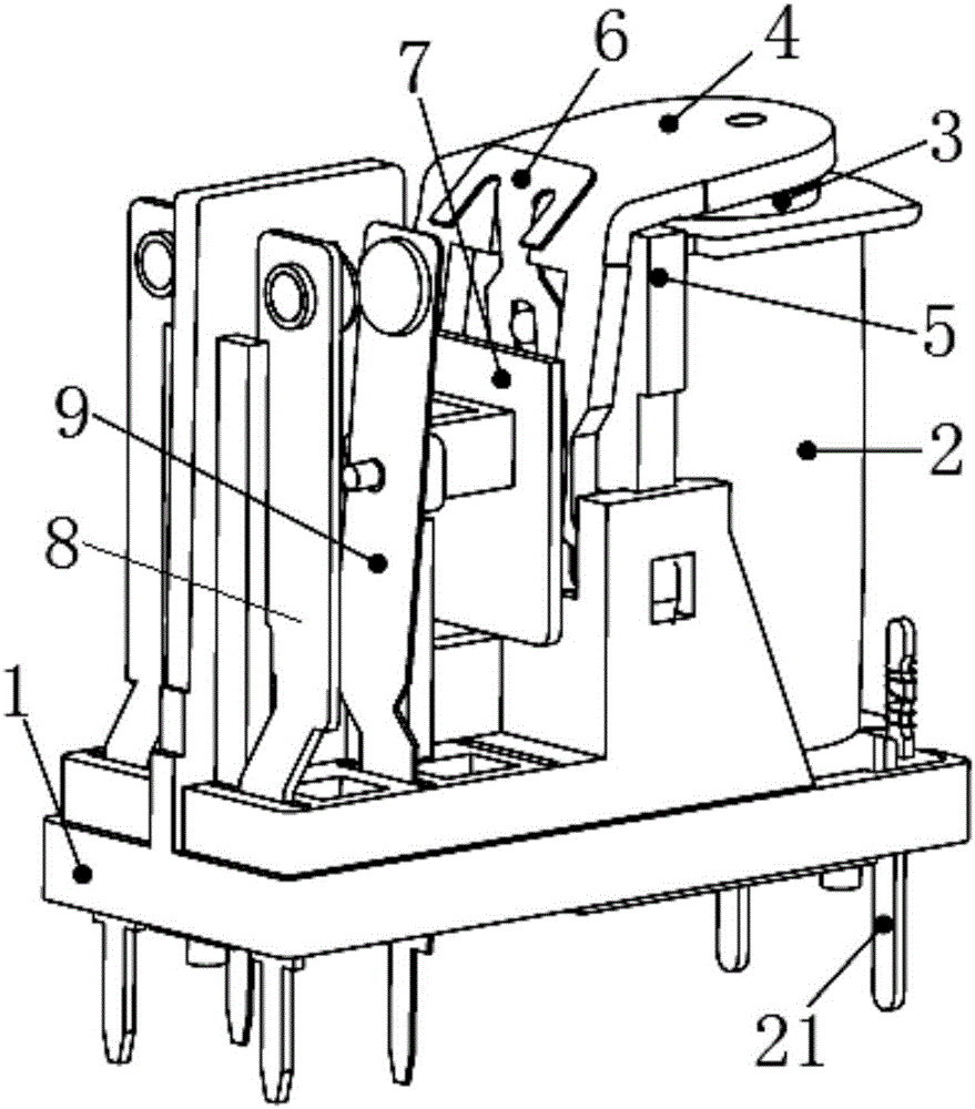
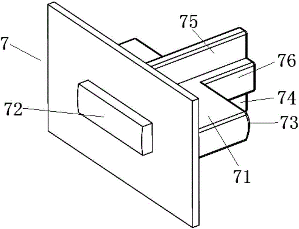
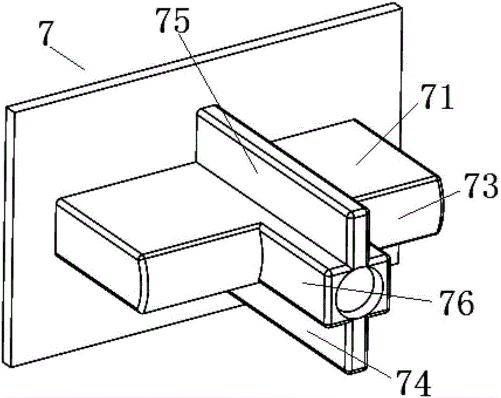
[0034] see figure 2 and image 3 As shown, the present invention is a push card structure applied to a push card relay, and the push card 7 has a push card body 71 with a plate-shaped structure. One end of the push card body 71 has an armature connection portion 72, and the other end has a moving spring connection portion 73, and a limit structure for linear displacement is provided on the push card body 71 near the armature connection portion 72, that is, the limit structure is The plate-shaped structure extends from the periphery of the push card body 71 . If the push card body 71 is the axial direction, the position-limiting structure is a plate-shaped structure formed in the radial direction of the push card body 71 .

[0035] The armature connection part 72 of the push card 7 is an outwardly convex arc surface structure, that is, the armature connection part 72 is an arch shape in the upper and lower directions of the end surface of the push card body 71, and the arc of...

Embodiment 2

[0039] The invention is a push card structure applied to a push card type relay, and the push card has a plate-shaped push card body. One end of the push card body has an armature connecting portion, and the other end has a moving spring connecting portion, and a linear displacement limiting structure is provided on the pushing card body near the armature connecting portion, that is, the limiting structure is a plate-shaped structure. The periphery of the push card body extends out. If the push card body is the axial direction, the position-limiting structure is a plate-shaped structure formed in the radial direction of the push card body.

[0040] The armature connection part of the push card is an outwardly convex arc surface structure, that is, the armature connection part is an arch shape in the upper and lower directions of the end surface of the push card body, and the arc of the arch can be specified according to the specific product. During use, the push card abuts aga...

Embodiment 3

[0044] The other content of this embodiment is the same as that of Embodiment 1 or 2, except that the linear sliding structure on the push card is formed in a linear chute (of course, it must be aligned with The structure on the relay base matches), specifically, the push card body at the rear of the limit structure is provided with a linear upper chute and a lower chute, and the upper chute is formed on the top surface of the push card body in a concave manner. The sliding groove is concavely formed on the bottom surface of the push card body.


PUM


Abstract

The invention relates to a relay push card structure and a relay containing the push card. The push card comprises a push card body. An armature connecting part is arranged at one end of the push card body, and the other end of the push card body is provided with a movable-spring connecting part. The armature connecting part is a cambered-surface structure protruding outwardly. The push card is in abutted contact with the armature of the relay through the cambered surface of the armature connecting part. The relay containing the push card comprises a base, a magnetic circuit part arranged on the base and a contact part, and the push card is assembled on a base between the magnetic circuit part and the contact part. The contact coordinated face, connected with the push card, of the armature is of a plane structure.

Description

technical field [0001] The invention relates to a relay, in particular to a relay pushing card structure and a relay including the pushing card. Background technique [0002] As the basic control component of the electrical system, the relay has been widely used in electromechanical equipment. There are various structures of existing relays, including push card relays. [0003] see figure 1 As shown, the existing push card relay is mainly composed of a base 1 , a magnetic circuit part and a contact part arranged on the base 1 and connected by a push card 7 . The magnetic circuit part is mainly composed of the iron core 3 arranged on the base 1, the coil 2 sleeved on the iron core 3, the yoke iron 5 arranged beside the coil 2, the armature 4 arranged on the end face of the iron core 3 by the seesaw effect, and The stage clip 6 that exerts spring force on the back of the armature 4 is formed. The contact part is mainly composed of a static reed 8 and a movable reed 9 arran...

Claims


Application Information

Patent Timeline
Patent Type & Authority Applications(China)
IPC IPC(8): H01H50/64
CPCH01H50/641
Inventor 王超高山谢明松
Owner SICHUAN HONGFA ELECTROACOUSTIC
Why Eureka
Try Eureka