
Heat sink for packaging laser chip array

A chip array and laser technology, applied in lasers, laser components, semiconductor lasers, etc., can solve the problems of unusable chip arrays, high production costs, and low yield of single-chip integrated array chips, and reduce the difficulty of packaging. The effect of improving placement accuracy

Inactive Publication Date: 2017-01-04
INST OF SEMICONDUCTORS - CHINESE ACAD OF SCI
View PDF6 Cites 3 Cited by
  • Summary
  • Abstract
  • Description
  • Claims
  • Application Information

AI Technical Summary

Problems solved by technology

And, if one chip doesn't work properly, the entire chip array becomes unusable
These problems make the yield of monolithic integrated array chips very low and the production cost is high

Method used


Image

  • Heat sink for packaging laser chip array
  • Heat sink for packaging laser chip array

Examples


Embodiment Construction

[0024] In order to make the object, technical solution and advantages of the present invention clearer, the present invention will be further described in detail below in conjunction with specific embodiments and with reference to the accompanying drawings.

[0025] The invention provides a heat sink for laser chip array packaging, which can be used not only for monolithic integrated array chips, but also for discrete chip array integration.

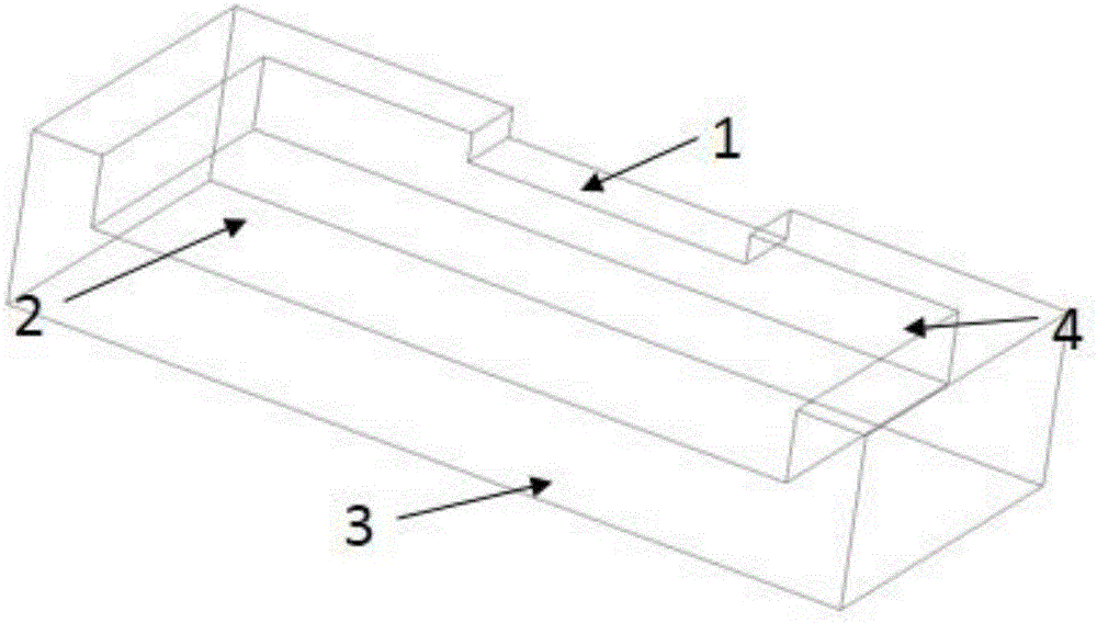
[0026] figure 1 A schematic diagram of a heat sink used for laser chip array packaging according to an embodiment of the present invention is schematically shown.

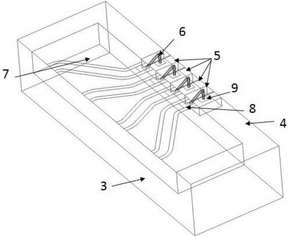
[0027] like figure 1 As shown, the heat sink includes: an array chip positioning groove 1 , a transmission line array plate positioning groove 2 , a heat sink substrate 3 and a positioning wall 4 . The positioning groove 2 of the transmission line array board is formed on the heat sink substrate 3 by a milling process, and a positioning wall 4 is formed around it, and the a...


PUM


Abstract

The invention discloses a heat sink for packaging a laser chip array. The heat sink for packaging the laser chip array comprises a heat sink substrate, a positioning wall, an array chip positioning groove and a transmission line array plate positioning groove. In the invention, the sizes of the array chip positioning groove and the transmission line array plate positioning groove respectively correspond to those of array chips and transmission line array plates; the depth of the transmission line array plate positioning groove is greater than that of the chip positioning groove to ensure that the transmission line array plates and the upper surface of the chip array are in a same plane. The positioning wall and the positioning grooves are used, so that the mounting precision is ensured, and the packaging difficulty is lowered.

Description

technical field [0001] The invention relates to the field of optoelectronic / microelectronic devices, in particular to a heat sink used for laser chip array packaging. Background technique [0002] With the rapid growth of optical communication capacity, higher speed requirements are put forward for optical emitting devices. However, it is difficult to meet the requirements of 100Gbps or 400Gbps transmission due to the limited improvement of the working rate of a single optical emitting device. The usual solution is to use a single-chip integrated multi-channel parallel light emitting array, that is, to integrate multiple laser chips with different operating wavelengths on the same substrate to meet the high-speed transmission requirements. However, the monolithic integration of multiple transmitter chips faces many difficulties. For example, there must be good electrical isolation between each chip in the chip array to reduce the impact of electrical crosstalk on device pe...

Claims


Application Information

Patent Timeline
Patent Type & Authority Applications(China)
IPC IPC(8): H01S5/024
CPCH01S5/02469
Inventor 张志珂刘宇祝宁华
Owner INST OF SEMICONDUCTORS - CHINESE ACAD OF SCI
Learn More