Motor

A technology of electric motor and frame, applied in the field of improvement of heat dissipation structure, can solve the problem that the electric motor is difficult to meet the requirements of the market and users

Active Publication Date: 2017-01-04
安徽华辰磁控科技有限公司
View PDF7 Cites 3 Cited by
  • Summary
  • Abstract
  • Description
  • Claims
  • Application Information

AI Technical Summary

Problems solved by technology

As the quality required by the market is getting higher and higher, it is difficult for this kind of motor to meet the requirements of the market and users

Method used


Image

  • Motor
  • Motor
  • Motor

Examples


Embodiment Construction

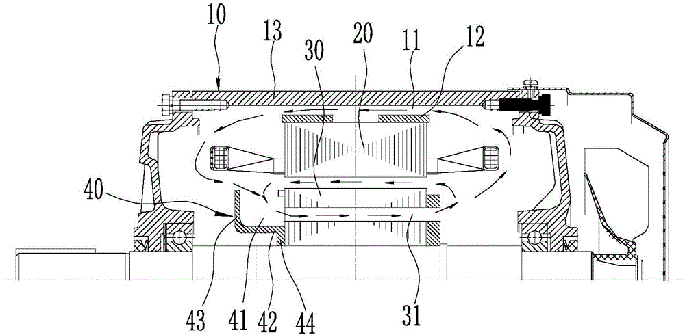
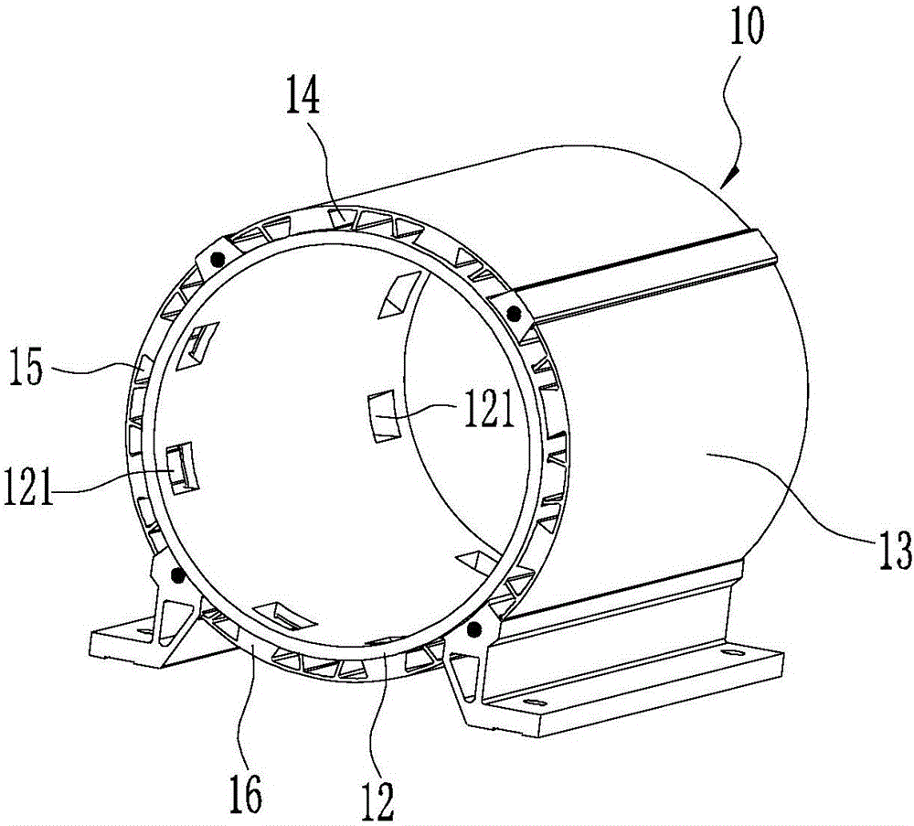
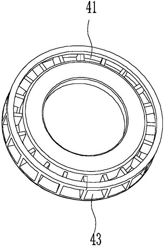
[0010] combine figure 1 , an electric motor, comprising a frame 10, a stator 20 and a rotor 30, characterized in that: a first air flow path 11 is arranged axially on the frame 10, and the two ends of the first air flow path 11 are respectively connected to the axial direction of the stator 20 On both ends, a vane windshield 40 is arranged at one end of the rotor 30, and the blade windshield 40 pushes the airflow to circulate along the airflow channel.

[0011] Since the first airflow path 11 is provided, combined with the airflow path formed by the air gap formed between the stator 20 and the rotor 30, the rotating shaft drives the blade windshield 40 to rotate synchronously when the motor is working, thereby pushing the airflow to circulate along the airflow path. The above scheme can timely and effectively exchange the heat in the motor chamber with the machine base, so that the motor can run in an ideal temperature environment.

[0012] As a preferred option, combined wit...


PUM


Abstract

The invention aims to provide a reluctance speed-regulating motor which improves circulating cooling efficiency and reduces temperature increase. The motor comprises a base, a stator and a rotor. A first air flow channel is configured in the axial direction on the base. Two ends of the first air flow channel are communicated with two end surfaces in the axial direction of the stator. One end of the rotor is provided with a blade air hood. Blade air hood pushing air current circularly flows along the air flow channel. According to the motor, because the first air flow channel is configured on the base along the axial direction, through an air supplying function of the blade air hood and the air flow channel which is formed by the air gap between the stator and the rotor, effective heat exchange between heat generated in motor operation and the base can be realized by means of circulating air flow can be realized, thereby greatly improving heat radiation efficiency of the motor. Particularly, a uniform heat radiation efficiency is realized, and a temperature environment in operation of the motor is improved.

Description

technical field [0001] The invention belongs to the structure of a reluctance speed-regulating motor, and specifically relates to an improvement of a heat dissipation structure of the motor. Background technique [0002] The heat dissipation structure of the motor has a great influence on its temperature rise, which directly affects the service life of the motor. At present, the traditional reluctance variable speed motor adopts the surface cooling method of the casing, that is, the heat generated in the motor is transferred to the surface of the casing through the self-circulation of the internal air of the motor, and the surface of the casing is cooled by the self-fan at the rear and the external air. The inside of the motor is divided into two cavities. The temperature rise of the part near the fan end is slightly lower, and the temperature of the part far away from the fan is higher. This structure is not conducive to the uniform heat dissipation of the motor. As the qu...

Claims


Application Information

Patent Timeline
Patent Type & Authority Applications(China)
IPC IPC(8): H02K5/20H02K9/04H02K1/32
CPCH02K1/32H02K5/20H02K9/04
Inventor 汪尧玉沈阳杨春华许洪清阮金晶吴学钎
Owner 安徽华辰磁控科技有限公司
Why Eureka
Try Eureka