Doherty amplifier

An amplifier and signal amplifying technology, applied in the direction of improving amplifiers to improve efficiency, etc., can solve the problems of power drop, fallback point efficiency drop, and the inability of Doherty amplifier to achieve sufficient impedance traction, and achieve large saturated output power and high fallback efficiency. , the effect of broad application prospects

Inactive Publication Date: 2017-01-04
SUZHOU INST OF NANO TECH & NANO BIONICS CHINESE ACEDEMY OF SCI
View PDF2 Cites 5 Cited by
  • Summary
  • Abstract
  • Description
  • Claims
  • Application Information

AI Technical Summary

Problems solved by technology

[0005] However, it is precisely because the auxiliary amplifier 13 works in the class C state, from figure 2 It can be seen that the power of the same amplifier working in class C is lower than that of class AB, which leads to the inability of the traditional symmetrical Doherty amplifier to achieve sufficient traction of impedance, resulting in a decrease in the efficiency of the fallback point

Method used


Image

  • Doherty amplifier
  • Doherty amplifier
  • Doherty amplifier

Examples


Embodiment Construction

[0026] Hereinafter, embodiments of the present invention will be described in detail with reference to the accompanying drawings. This invention may, however, be embodied in many different forms and should not be construed as limited to the specific embodiments set forth herein. Rather, the embodiments are provided to explain the principles of the invention and its practical application, thereby enabling others skilled in the art to understand the invention for various embodiments and with various modifications as are suited to particular intended uses. In the drawings, the same reference numerals may be used to refer to the same elements throughout the specification and drawings.

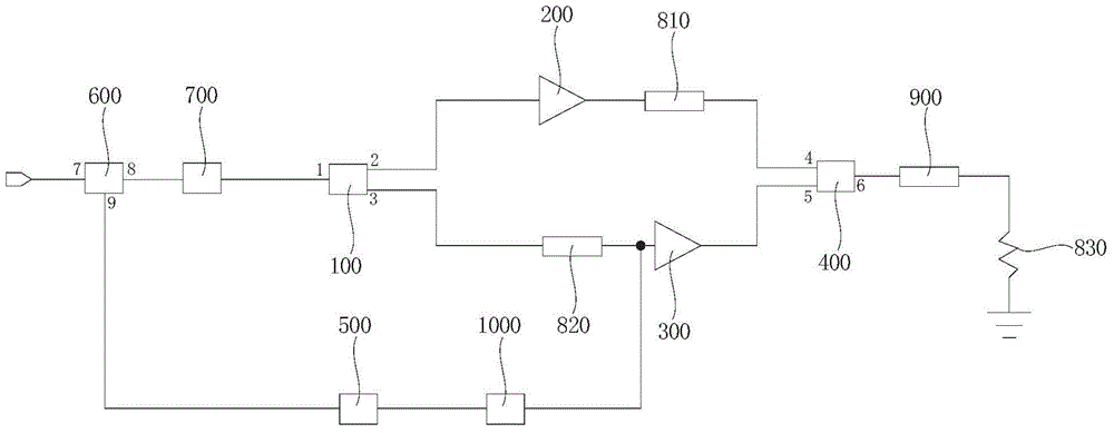
[0027] image 3 is a circuit configuration diagram of the Doherty amplifier according to the first embodiment of the present invention.

[0028] refer to image 3 , the Doherty amplifier according to the first embodiment of the present invention includes: a branching module 100 , a first power a...


PUM


Abstract

The invention discloses a Doherty amplifier comprising a shunt module used for separating a part of to-be-amplified signals, wherein a first output end and a second output end of the shunt module separately output the part of to-be-amplified signals after shunting; a first power amplifier module used for amplifying the signals from the first output end of the shunt module and outputting the amplified signals to a first input end of a combiner module; a second power amplifier module used for amplifying the signals from the second output end of the shunt module and outputting the amplified signals to a second input end of the combiner module; the combiner module used for combining the amplified signals; and a grid voltage regulation and control module used for regulating a grid bias voltage provided by a low pass filtering module for the second power amplifier module according to the magnitude of another part of to-be-amplified signals. The Doherty amplifier disclosed by the invention can provide greater saturated output power and higher fallback efficiency, and has broad application prospects for application occasions requiring high-efficiency amplifiers, such as base stations and so on.

Description

technical field [0001] The invention relates to a Doherty amplifier, in particular to a Doherty amplifier with a high-efficiency signal amplification function. Background technique [0002] The theory of the Doherty amplifier was proposed by W.H.Doherty in 1936. Its purpose is to solve the shortcoming of low efficiency when the ordinary Class AB power amplifier works at the power back-off point. The traditional Doherty power amplifier consists of a main amplifier and an auxiliary amplifier. composition. [0003] figure 1 Is the circuit diagram of the traditional Doherty amplifier. Such as figure 1 As shown, the input signal splitting unit 11 divides the signal into two paths, which are respectively used to drive the main amplifier 12 and the auxiliary amplifier 13 . The main amplifier 12 is connected to the auxiliary amplifier 13 through the first λ / 4 transmission line 14, the first λ / 4 transmission line 14 plays the role of impedance inversion; the second λ / 4 transmissi...

Claims


Application Information

Patent Timeline
Patent Type & Authority Applications(China)
IPC IPC(8): H03F1/07
Inventor 侯富诚宋贺伦顾滕锋曾大杰张耀辉
Owner SUZHOU INST OF NANO TECH & NANO BIONICS CHINESE ACEDEMY OF SCI
Why Eureka
Try Eureka