
Semiconductor optical amplifier

An optical amplifier and semiconductor technology, applied in instruments, optics, nonlinear optics, etc., can solve the problems of inconvenient process, inconvenient application, complex structure, etc., and achieve the effect of high particle number inversion, easy implementation and simple structure.

Inactive Publication Date: 2008-01-16
HUAZHONG UNIV OF SCI & TECH
View PDF5 Cites 0 Cited by
  • Summary
  • Abstract
  • Description
  • Claims
  • Application Information

AI Technical Summary

Problems solved by technology

[0007] The invention provides a semiconductor optical amplifier, which solves the technical problems of complex structure, difficult process and inconvenient application, and has both high saturated output power and low noise index

Method used


Image

  • Semiconductor optical amplifier

Examples


Embodiment Construction

[0020] The present invention will be further described below in conjunction with the embodiments and accompanying drawings.

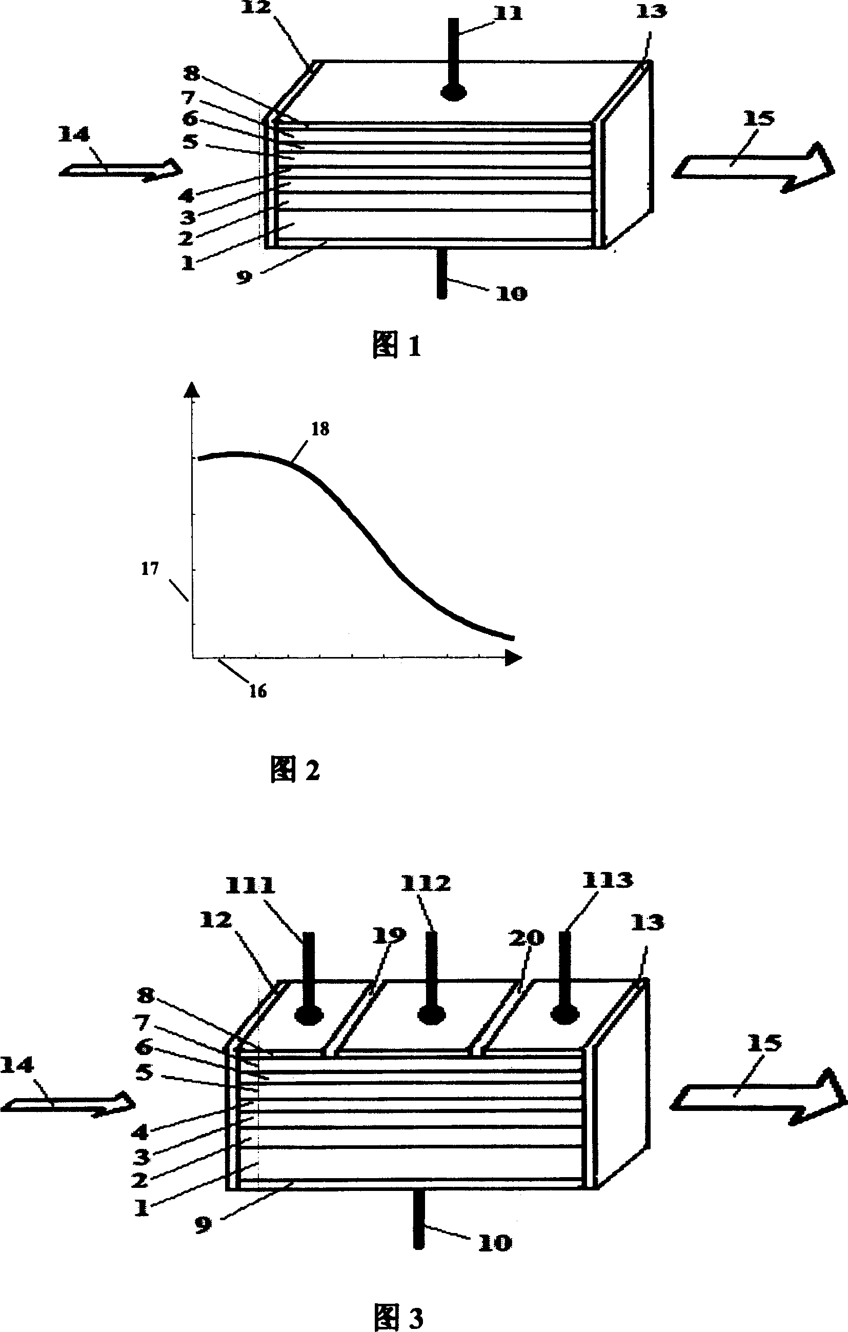
[0021] Fig. 3 is a structural schematic diagram of an embodiment of the present invention. The SOA shown is a typical structure in which quantum wells are used as the active region. Its interior consists of a substrate 1, a buffer layer and a lower cladding layer 2, a lower confinement layer 3, an active region 4, an upper confinement layer 5, and an upper cladding layer. 6. The ohmic contact layer 7 is formed sequentially. An anti-reflection film 12 and an anti-reflection film 13 are plated on the input end face and output end face of the amplifier. The top layer and the bottom layer of the amplifier are the upper metal electrode layer 8 and the lower metal electrode layer 9 respectively; the lower electrode 10 is made under the lower metal electrode layer 9 . The input signal light 14 enters the interior of the SOA, and it can be continuously amplif...


PUM


Abstract

The invention relates to a semiconductor optic element of light amplifier, which comprises the following parts: substrate, breaker, up-envelope, active region, down-envelop, ohmic contact layer, top or bottom chip with up or down metal electrode separately, anti-reflection film plated on the input and output end face of amplifier. The reflectance of anti-reflection film output end face is less than input end face. There are N electric insulating slots, which are etched on the top of the metal electrode, which divide amplifier into N+1 annellus (each annelet has an up-electrode, N>=2) along the tune direction. The invention improves SOA noise index and saturated outcoming power.

Description

technical field [0001] The invention belongs to semiconductor optoelectronic devices, in particular to a semiconductor optical amplifier with high saturated output power and low noise index. Background technique [0002] Semiconductor Optical Amplifier (SOA: Semiconductor Optical Amplifier) ​​will play an important role in all-optical communication systems due to its small size, low cost, and easy integration with other optoelectronic devices, especially in metropolitan area networks and access networks. The distance and transmission rate are small, and the number of channels is not many. Therefore, from the perspective of cost performance, the use of semiconductor optical amplifiers is more cost-effective than optical fiber amplifiers; Figure 1 is a representative structural diagram of an existing SOA, see "1.55 Research on μm AlGaInAs-InP Polarization-Independent Semiconductor Optical Amplifier and Its Temperature Characteristics" Ma Hong, Chen Sihai, Jin Jinyan, Yi Xinjia...

Claims


Application Information

Patent Timeline
Patent Type & Authority Patents(China)
IPC IPC(8): G02F1/39
Inventor 刘德明黄黎蓉陈俊柯昌剑
Owner HUAZHONG UNIV OF SCI & TECH
Learn More