Rendering method and system for focusing light field camera

A light field camera and refocusing technology, which is applied to TV system parts, color TV parts, TVs, etc., can solve the problems affecting the rendering rate and the large amount of calculation of the rendering method, so as to improve image quality and image quality. Clear, computationally-reduced effect

Active Publication Date: 2019-09-13
SHENZHEN INST OF FUTURE MEDIA TECH +1
View PDF6 Cites 0 Cited by
  • Summary
  • Abstract
  • Description
  • Claims
  • Application Information

AI Technical Summary

Problems solved by technology

[0005] In the traditional rendering method, the shape of the area block is square, and the microlens array of the focusing light field camera is usually arranged in a regular hexagon, so in the rendering process, it is necessary to go through a regular hexagonal coordinate system The conversion to the orthogonal coordinate system requires a large amount of calculation for the rendering method, which affects the rendering rate

Method used


Image

  • Rendering method and system for focusing light field camera
  • Rendering method and system for focusing light field camera
  • Rendering method and system for focusing light field camera

Examples


Embodiment Construction

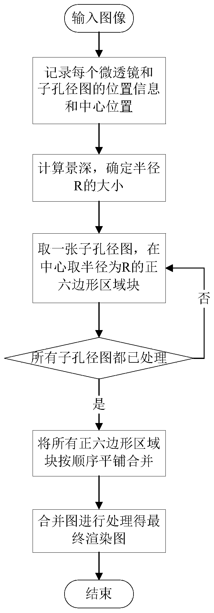
[0032] The embodiment of the present invention will be further described below in conjunction with the accompanying drawings, the specific process is as follows, and its flow diagram is as follows figure 1 shown.

[0033] S1. Input the picture taken by the focused light field camera, and record the position information and center position of each microlens and sub-aperture map.

[0034] S2. Calculate the depth of field of the planar image that needs to be refocused, and determine the size of the radius R according to the depth of field.

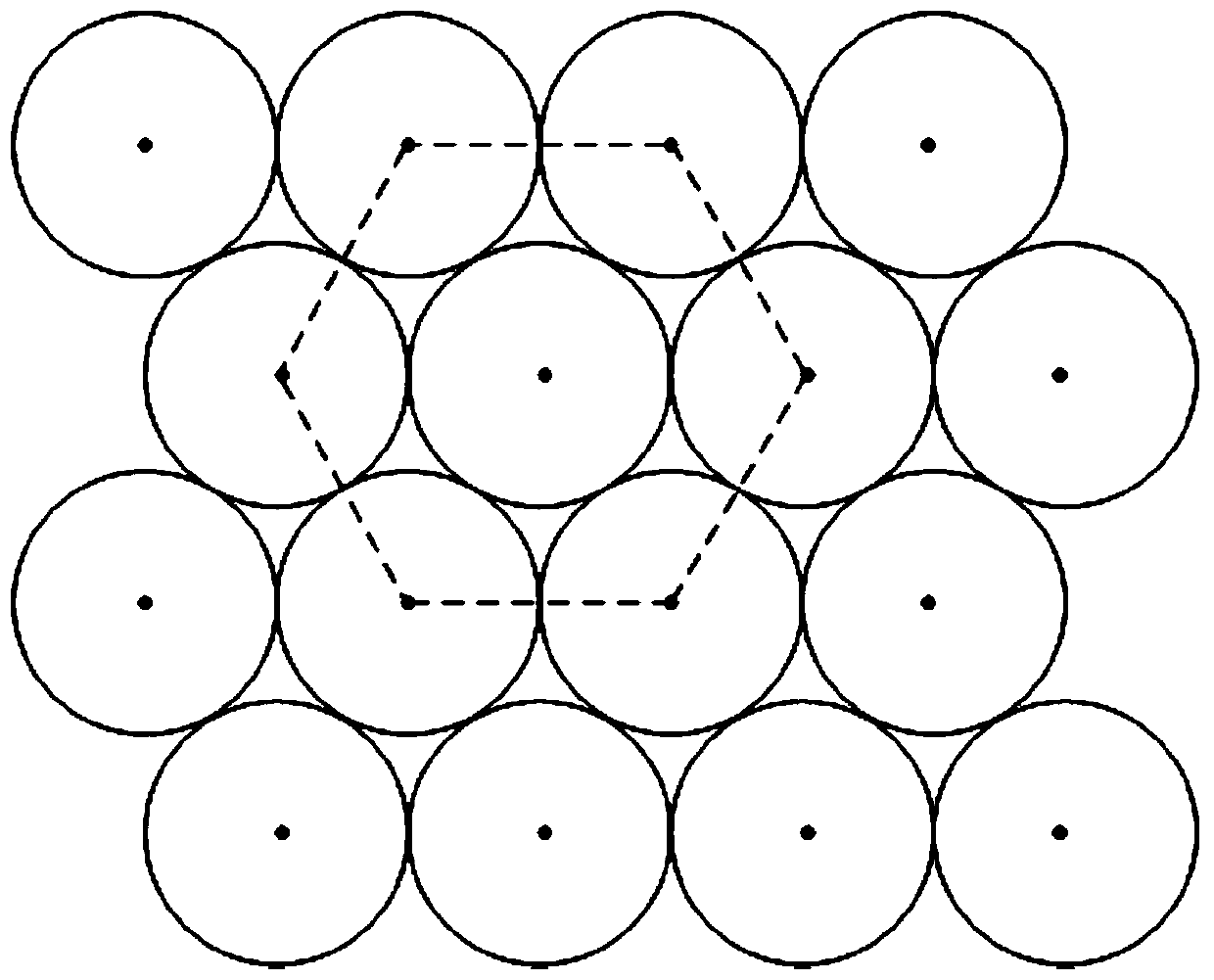
[0035] S3. At the center of each sub-aperture map, take a regular hexagonal block with a radius R.

[0036] S4. Tiling and merging the regular hexagonal area blocks in the order of the sub-aperture diagrams to obtain a merged diagram;

[0037] S5. Process the merged image to obtain a final rendered image.

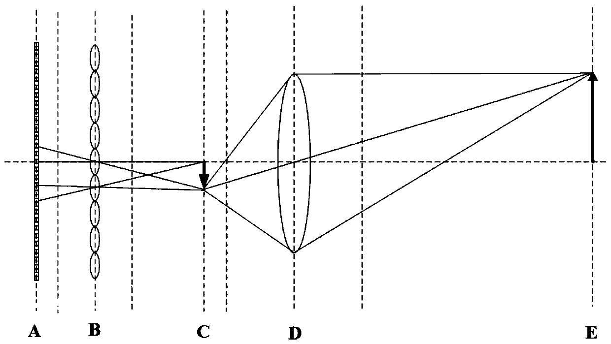
[0038] A light field camera is a device for obtaining light field information, including a four-dimensional light radiation field incl...


PUM


Abstract

The invention discloses a rendering method and system of a focused light field camera, the method comprising: S1. Inputting a picture taken by a focused light field camera, and recording the position information and center position of each microlens and sub-aperture image; S2. Calculate its depth of field according to the plane image that needs to be refocused, and determine the size of the radius R according to the depth of field; S3. At the center of each sub-aperture map, take a regular hexagonal block with a radius of R; S4. Make the regular hexagonal The region blocks are tiled and merged according to the order of the sub-aperture images to obtain a merged image; S4. Processing the merged image to obtain a final rendered image. This method takes advantage of the hexagonal arrangement characteristics of the microlens array, and takes regular hexagonal blocks for the microlens sub-aperture diagram. In the rendering process, it does not need to transform the coordinate system, which can effectively reduce the rendering of the focused light field camera. The calculation amount of the method.

Description

technical field [0001] The invention belongs to the technical field of rendering of a light field camera, and in particular relates to a rendering method and system of a focusing light field camera. Background technique [0002] A light field camera is a device that can record light direction and position information. Compared with traditional cameras, it has an additional microlens array in structure. The process of using this device to obtain images is called light field imaging. As a new direction in imaging technology, light field imaging can achieve refocusing without mechanical focusing after shooting, but can achieve refocusing through image processing calculations, and can achieve 3D reconstruction and multi-target point focusing. These characteristics make it in There will be a lot of room for development in future life. [0003] The light field camera can simultaneously capture the spatial (or position) and direction (or angle) information of the scene, that is, t...

Claims


Application Information

Patent Timeline
Patent Type & Authority Patents(China)
IPC IPC(8): H04N5/232H04N5/225
CPCH04N23/957H04N23/55H04N23/959H04N23/67H04N23/00
Inventor 王好谦刘帝刘烨斌王兴政张永兵戴琼海
Owner SHENZHEN INST OF FUTURE MEDIA TECH
Why Eureka
Try Eureka