
Signal high-fidelity wireless audio receiving system

An audio reception, high-fidelity technology, applied in the field of wireless transmission, can solve the problem of loud noise in sound playback, and achieve the effect of clean audio signal, improved clarity, and stable static operating point

Inactive Publication Date: 2017-01-04
成都云材智慧数据科技有限公司
View PDF0 Cites 2 Cited by
  • Summary
  • Abstract
  • Description
  • Claims
  • Application Information

AI Technical Summary

Problems solved by technology

[0003] The purpose of the present invention is to solve the defect that the current audio signal is affected by the interference signal during the wireless transmission process and cause a lot of noise in the sound playback, and to provide a signal high-fidelity wireless audio receiving system

Method used


Image

  • Signal high-fidelity wireless audio receiving system
  • Signal high-fidelity wireless audio receiving system

Examples


Embodiment

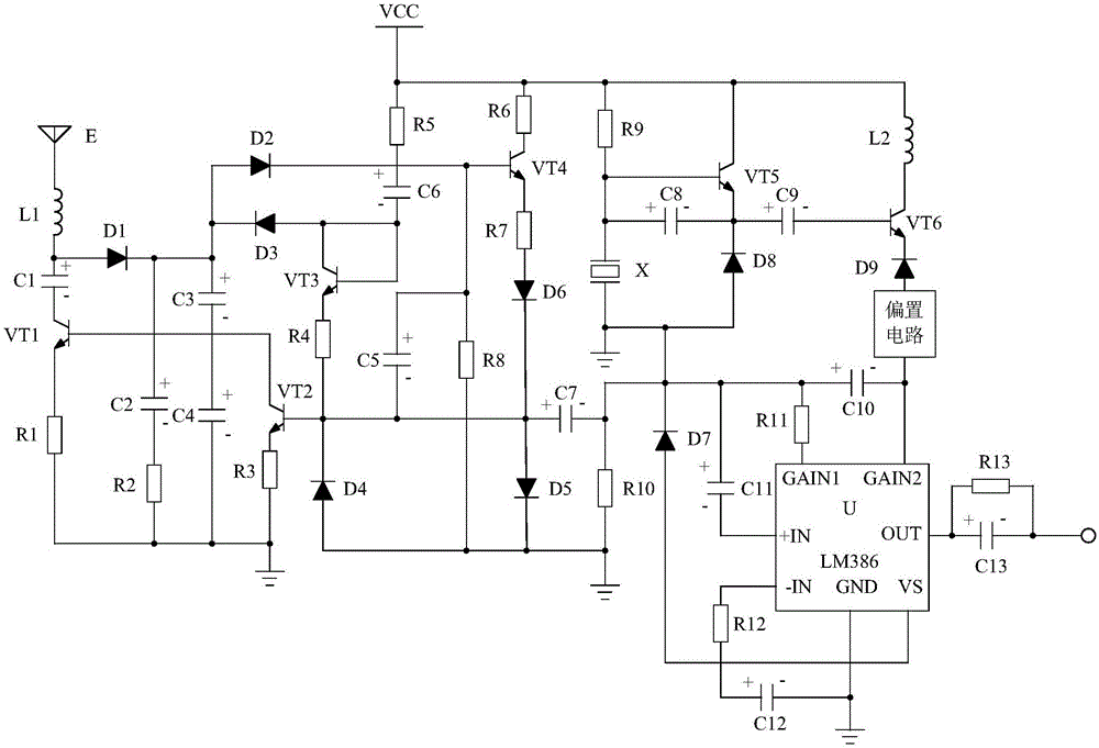
[0018] Such as figure 1 As shown, the present invention mainly consists of the processing chip U, the positive pole is connected to the -IN pin of the processing chip U through the resistor R12, the negative pole is connected to the GND pin of the processing chip U and the capacitor C12 is grounded at the same time, and the positive pole is connected to the processing chip. The OUT pin of U is connected to the capacitor C13 with the negative electrode as the output terminal, the resistor R13 connected in parallel with the capacitor C13, the bias circuit connected to the GAIN2 pin of the processing chip U, the oscillator circuit connected to the bias circuit, and The audio signal compression circuit connected to the oscillation circuit, the front-end receiving circuit connected to the audio signal compression circuit, the P pole is connected to the VS pin of the processing chip U, the N pole is connected to the oscillating circuit, and the diode D7 is connected to the processing c...


PUM


Abstract

The invention discloses a signal high-fidelity wireless audio receiving system. The system is characterized by mainly consisting of a processing chip, a capacitor C12, a capacitor C13 and the like, wherein the anode of the capacitor C12, after passing through a resistor R12, is connected with the -IN pin of the processing chip U, the cathode of the capacitor C12 is connected with the GND pin of the processing chip U, the capacitor C12 is grounded at the same time, the anode of the capacitor C13 is connected with the OUT pin of the processing chip U, and the cathode of the capacitor C13 is taken as an output end. According to the invention, interference signals doped in audio signals in a wireless transmission process can be filtered at a receiving end and an output end, the interference signals are filtered by use of a dual-filtering mode, the filtering effect is enabled to be more thorough, the output audio signals are cleaner, the play quality of sound is improved, and the hearing effect of people is enabled to be better.

Description

Technical field [0001] The invention relates to the field of wireless transmission, in particular to a signal high-fidelity wireless audio receiving system. Background technique [0002] The wireless audio signal transmission system is composed of a wireless transmitting system and a wireless receiving system. It is used for long-distance wireless transmission of audio signals. It has been widely used in people's lives and brought great convenience to people's lives. With the continuous improvement of people's living standards, people have higher and higher requirements for sound quality. However, the wireless audio signal transmission system usually has interference signals doped into the audio signals during the wireless transmission of audio signals. Due to the influence of the interference signals, the sound output at the receiving end will have a lot of noise. Seriously affect people's hearing effect. Therefore, it is an urgent task to improve a new type of wireless receiv...

Claims


Application Information

Patent Timeline
Patent Type & Authority Applications(China)
IPC IPC(8): H04R3/00
CPCH04R3/00
Inventor 向勇宋世湃吴露朱焱麟
Owner 成都云材智慧数据科技有限公司
Learn More