
LED-COB optical engine driving device

A technology of LED-COB and driving device, applied in lighting device, light source, electric light source, etc., to achieve the effect of reducing heat dissipation temperature and prolonging service life

Inactive Publication Date: 2017-01-04
GUANGDONG POLYTECHNIC NORMAL UNIV
View PDF0 Cites 0 Cited by
  • Summary
  • Abstract
  • Description
  • Claims
  • Application Information

AI Technical Summary

Problems solved by technology

Based on the comprehensive consideration of the light efficiency and life of the LED planar light source module, regardless of the power, the most ideal method is to control the junction temperature of the LED planar light source below 60°C. Although the LED-COB light source heat dissipation device has been greatly improved, but LED-COB runs at high power for a long time, and it is inevitable to control the junction temperature not to exceed the limit

Method used


Image

  • LED-COB optical engine driving device

Examples


Embodiment 1

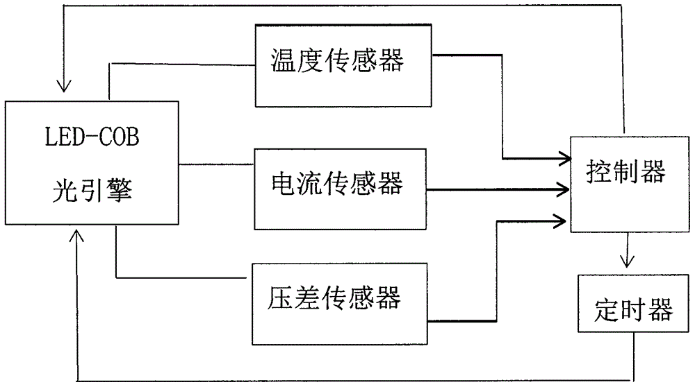
[0018] The present invention provides a technical solution: an LED-COB light engine driving device, including a temperature sensor 1, a current sensor 2, a differential pressure sensor 3, and a controller 4;

[0019] The temperature sensor 1 is set to detect the temperature of the LED-COB substrate;

[0020] The current sensor 2 is used to detect the current in the LED-COB circuit;

[0021] The differential pressure sensor 3 is used to detect the differential pressure across the LED-COB circuit;

[0022] The controller 4 is set to control the LED-COB according to the temperature detected by the temperature sensor 1

[0023] Wherein the controller 4 controls the voltage difference across the LED-COB circuit according to the comparison result of the temperature detected by the temperature sensor 1 and the stored intensity data to keep the light output of the LED-COB in different colors, and the intensity data is related to the temperature and The color of the LED-COB is associ...

Embodiment 2

[0026] The present invention provides a technical solution: an LED-COB light engine driving device, including a temperature sensor 1, a current sensor 2, a differential pressure sensor 3, and a controller 4;

[0027] The temperature sensor 1 is set to detect the temperature of the LED-COB substrate;

[0028] The current sensor 2 is used to detect the current in the LED-COB circuit;

[0029] The differential pressure sensor 3 is used to detect the differential pressure across the LED-COB circuit;

[0030] The controller 4 is set to control the driving current of the LED-COB light engine according to the temperature detected by the temperature sensor 1 .

[0031] Wherein the controller 4 controls the voltage difference across the LED-COB circuit to keep the light output of the LED in different colors according to the comparison result of the temperature detected by the temperature sensor 1 and the stored intensity data, and the intensity data is related to the temperature and t...


PUM


Abstract

The invention relates to the technical field of LED illumination, and specifically relates to an LED-COB optical engine driving device. The LED-COB optical engine driving device comprises a temperature sensor 1, a current sensor 2, a pressure difference sensor 3 and a controller 4, the temperature sensor 1 is used for detecting the temperature of an LED-COB substrate, the current sensor 2 is used for detecting current in an LED-COB circuit, the pressure difference sensor 3 is used for detecting the pressure difference between two ends of the LED-COB circuit, and the controller 4 is used for controlling the LED-COB optical engine driving current according to the temperature detected by the temperature sensor 1. The pressure difference between two ends of the LED-COB circuit is controlled by a comparison result of the temperature detected by the temperature sensor 1 and stored strength data to maintain the light of the LED to output different colors, and the strength data and the temperature are associated with the colors of the LED; and when a set time is arrived, the controller 4 is triggered to output the current, and the LED-COB optical engine performs switching of turn-on and turn-off.

Description

technical field [0001] The invention relates to the technical field of LED lighting lamps, in particular to an LED-COB light engine driving device. Background technique [0002] In recent years, many international first-line lighting brand companies have begun to deploy intelligent control fields such as sensing, communication, and multimedia. Through cross-field cooperation, we provide customers with comprehensive services and system solutions. At present, although some domestic enterprises have launched intelligent lighting products, most of them only stay in simple dimming and color matching. The lower the junction temperature of the LED-COB planar light source, the longer the service life. Based on the comprehensive consideration of the light efficiency and life of the LED planar light source module, regardless of the power, the most ideal method is to control the junction temperature of the LED planar light source below 60°C. Although the LED-COB light source heat dis...

Claims


Application Information

Patent Timeline
Patent Type & Authority Applications(China)
IPC IPC(8): H05B33/08H05B44/00
CPCH05B45/14H05B45/40H05B45/50
Inventor 姚屏
Owner GUANGDONG POLYTECHNIC NORMAL UNIV
Learn More