
Inferior vena cava root blood vessel anatomic separating forceps applied to laparotomy

A technology of vena cava and separation forceps, which is applied in the field of anatomical separation forceps, can solve the problems of uncomfortable operation, damage to large blood vessel walls, bleeding, and low separation efficiency, and achieve the effects of low cost, shortened operation time, and reasonable structural design

Inactive Publication Date: 2017-01-11
李楠 +1
View PDF5 Cites 2 Cited by
  • Summary
  • Abstract
  • Description
  • Claims
  • Application Information

AI Technical Summary

Problems solved by technology

When the operator uses the above alternative instruments to separate the blood vessels at the root of the vena cava, especially the posterior side wall of the hepatic vein, he needs to grasp the top of the diaphragm with one hand and pull the liver downward to expose the second hepatic hilum. One hand holding an alternative instrument needs to constantly change the way of holding the forceps to adapt to the anatomical position of the separated part of the root of the inferior vena cava. The separation efficiency is low and the operation is uncomfortable. In addition, the more worrying thing is that the way of holding the forceps is not smooth It is very easy to damage the wall of the large blood vessel under the operation, resulting in a large amount of bleeding

Method used


Image

  • Inferior vena cava root blood vessel anatomic separating forceps applied to laparotomy
  • Inferior vena cava root blood vessel anatomic separating forceps applied to laparotomy

Examples


Embodiment

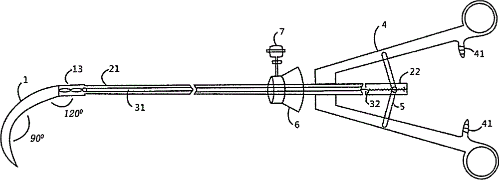
[0025] As shown in the figure, the present invention is an anatomical separating forceps specially used for separating blood vessels at the root of the vena cava in laparotomy.

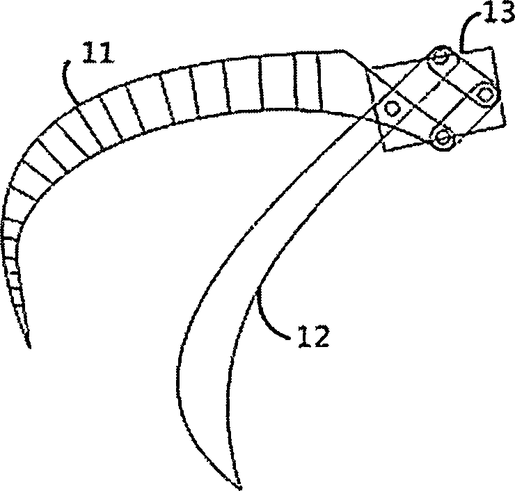
[0026] The head-end separation part 1 is formed by hinges of the forceps blade 11 and the forceps blade 12 through the hinge device 13, and the inner sides of the two forceps blades are arranged in a tooth-like structure that coincides with each other;

[0027] The two parts of the gripping device 4 are fixed symmetrically to the first section 21 of the pliers rod, and the inner side of the gripping device is provided with mutually matched tooth buckles 41 for locking the functional state of the instrument;

[0028] Two symmetrical connecting rods 5 are respectively hinged to the second section 22 of the clamp rod and the holding device 4;

[0029] The clamp rod is hollow, two soft steel wires 31 run inside the first section 21, and a spring 32 is set inside the second section 22; the two ends of the ...


PUM


Abstract

The invention belongs to the field of medical apparatuses, and relates to a pair of anatomic separating forceps for separating vena cava root blood vessels in laparotomy. The pair of anatomic separating forceps comprises a head end separating portion, a forceps rod, a connecting device, a holding device, connecting rods, a rotating wheel and a punching piece; the pair of anatomic separating forceps is characterized in that the main bodies of two forceps blades of the head end separating portion form a right angle, and the entire separating portion forms a 120-degree arc-shaped included angle with the forceps rod; the forceps rod is hollowed and is composed of two sections, and the connecting device is arranged in the forceps rod; two flexible steel wires are arranged in the first section, and the flexible steel wires are connected to the separating portion and a spring in the second section; the two symmetrical connecting rods are hinged with the second section of the forceps rod and the holding device; the rotating wheel is arranged on the forceps rod, so that the separating portion is rotated; and the punching device is arranged on the rotating wheel and communicates with the interior of the rotating wheel and the connecting device. The pair of anatomic separating forceps provided by the invention is reasonable in structural design and strong in practicability, and the safety and the efficiency of separating the inferior vena cava root blood vessels can be improved.

Description

[0001] Technical field [0002] The invention relates to an anatomical separating forceps used for separating blood vessels at the root of the inferior vena cava in laparotomy, and belongs to the technical field of medical instruments. Background technique [0003] The second porta hepatis is the part where the three hepatic veins (right, middle, and left) meet with the inferior vena cava. It is the main outflow channel of blood flow to the liver. It is located deep and close to the diaphragm. During liver surgery, it is often necessary to separate and ligate one or two hepatic veins to cut off the blood flow out of the liver in this area. At present, there is no special forceps for separating blood vessels at the root of the vena cava clinically, and large-scale thoracic forceps or Right-angle vascular clamps instead. Due to the particularity and importance of the anatomical location of the root of the vena cava, the above alternative devices are unsatisfactory in terms of t...

Claims


Application Information

Patent Timeline
IPC IPC(8): A61B17/28
CPCA61B17/2812A61B17/2841A61B2017/00778A61B2017/2845
Inventor 李楠张龙程树群卫旭彪孙居仙钟承千段花玲
Owner 李楠
Learn More