
Indwelling needle

An indwelling needle and isolation plug technology, applied in the field of indwelling needles, can solve the problem that the dead space cannot be flushed in real time by the liquid medicine, and achieve the effects of improving security, reducing chemical reactions, and improving life safety.

Active Publication Date: 2017-01-11
DRAGON HEART MEDICAL DEVICES
View PDF8 Cites 0 Cited by
  • Summary
  • Abstract
  • Description
  • Claims
  • Application Information

AI Technical Summary

Problems solved by technology

[0004] Therefore, the technical problem to be solved by the present invention is to overcome the defect that the indwelling needle in the prior art cannot be washed in real time by the liquid medicine at the dead space formed between the isolation plug and the inner wall of the inner cavity on the side away from the liquid inlet, thereby providing An indwelling needle that can be flushed by liquid medicine in real time at the dead space formed between the isolation plug and the inner wall of the inner cavity on the side away from the liquid inlet, reducing the harm to the patient

Method used


Image

  • Indwelling needle
  • Indwelling needle
  • Indwelling needle

Examples


Embodiment 1

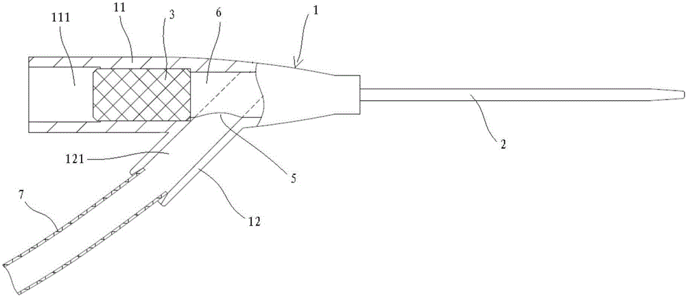
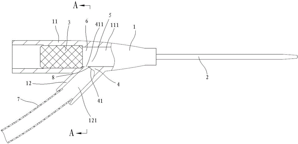
[0040] Such as figure 2 As shown, this embodiment provides an indwelling needle, which includes a catheter base 1 , a catheter 2 , an isolation plug 3 and a liquid blocking bump 4 .

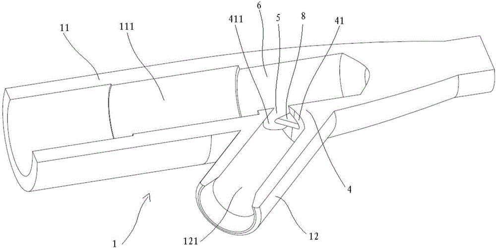
[0041] The catheter adapter 1 is composed of a main body 11 with an inner cavity 111 and a side connection tube 12 connected to the side wall of the main body 11 with a lumen 121. The lumen 121 is set at an angle with the inner cavity 111 and communicates with the liquid inlet 5. And one end of the side connecting pipe 12 connected to the liquid inlet 5 faces the conduit 2 .

[0042] The catheter 2 is arranged at one end of the main body 11 , and its infusion tube core communicates with the inner cavity 111 .

[0043] The isolation plug 3 is accommodated in the inner cavity 111 , and is separated from the catheter 2 in the inner cavity 111 on both sides of the connection between the lumen 121 and the inner cavity 111 .

[0044] The liquid blocking protrusion 4 and the liquid inlet 5 of the lumen...

Embodiment 2

[0052] This embodiment provides an indwelling needle, which is different from Embodiment 1 in that the location of the liquid blocking protrusion 4 is different.

[0053] In this embodiment, the liquid blocking protrusion 4 and the inner wall of the inner cavity 111 on the side away from the isolation plug 3 at the liquid inlet 5 of the inner cavity 111 are integrally formed. The surface 41 and the edge of the liquid inlet 5 near the side of the isolation plug 3 form a diversion opening 411 .

Embodiment 3

[0055] refer to Figure 5 , this embodiment provides an indwelling needle, which differs from Embodiment 1 in that:

[0056] In this embodiment, there is no liquid blocking bump 4 in Embodiment 1;

[0057] In this embodiment, an extension tube 7 is also included, which is connected to one end of the side connection pipe 12 opposite to the liquid inlet 5. The extension pipe 7 passes through the liquid inlet 5 of the side connection pipe 12 and extends into the inner cavity 111, and the extension pipe 7 extends into the inner cavity. The portion in cavity 111 is the nozzle portion. The nozzle part is bent toward the isolation plug 3 and includes a first extension wall 71 formed on the top of the tube wall away from the isolation plug 3 , and the first extension wall 71 is bent toward the isolation plug 3 side.

[0058] When the indwelling needle of this embodiment is in use, the liquid medicine flows in from the extension tube 7 and is blocked by the first extension wall 71 wh...


PUM


Abstract

The invention provides an indwelling needle. The indwelling needle comprises a catheter base, a catheter, an insulated plug and a diversion structure, wherein the catheter base consists of a main body with an inner cavity and a side connecting pipe which is connected onto the side wall of the main body and is provided with a pipe cavity; the pipe cavity is communicated with the inner cavity at a liquid inlet; the catheter is arranged at one end of the main body; an infusion pipe core of the catheter is communicated with the inner cavity; the isolated plug is accommodated in the inner cavity; the isolated plug and the catheter are separately arranged at two sides of a communicated part between the pipe cavity and the inner cavity in the inner cavity; the diversion structure is arranged at the liquid inlet, and enables liquid flow facing the isolated plug to be formed at the liquid inlet. By arrangement of the diversion structure, a dead cavity formed between the isolated plug and the inner wall of the inner cavity away from one side of the liquid inlet can be flushed in real time, thereby quickly exhausting air, blood, residual liquid medicine and the like in the dead cavity, preventing embolism due to the fact that air enters a human body, preventing the condition that blood vessels are blocked by thrombus due to the fact that coagulated blood at the dead cavity is flushed into the blood vessels, avoiding the phenomenon that the medicinal effect is reduced because of a chemical reaction between residual liquid medicine at the dead cavity and newly-inputted liquid medicine, and improving the guarantee of life safety of a patient.

Description

technical field [0001] The invention relates to the technical field of medical equipment, in particular to an indwelling needle. Background technique [0002] In the medical field, such as figure 1 As shown, the indwelling needle used for clinical patients usually includes a catheter 2, a catheter adapter 1, an extension tube 7, and an isolation plug 3, etc., wherein the catheter adapter 1 includes a main body 11 and a side connecting pipe 12, and the main body 11 is formed with a Inner cavity 111, the catheter 2 is installed at one end of the main body 11 and communicated with the inner cavity 111, the isolation plug 3 is accommodated in the inner cavity 111, and the cavity wall of the inner cavity 111 is between the isolation plug 3 and the catheter 2 There is a liquid inlet 5 connected to the side connection pipe 12 at the position, and the extension pipe 7 is connected to the side connection pipe 12 and communicated with the inner cavity 111. The liquid medicine in the ...

Claims


Application Information

Patent Timeline
IPC IPC(8): A61M5/158
CPCA61M5/158
Inventor 黄永强赵善铭梁永基
Owner DRAGON HEART MEDICAL DEVICES
Learn More