Silicon steel plate stamping production line

A silicon steel sheet and production line technology, applied in the direction of feeding device, positioning device, storage device, etc., can solve the problems of unreasonable layout of stamping production line and low production efficiency, and achieve the effect of simple structure, improved production efficiency and reasonable layout

Active Publication Date: 2017-01-11
WUXI IDO SCI & TECH CO LTD
View PDF6 Cites 14 Cited by
  • Summary
  • Abstract
  • Description
  • Claims
  • Application Information

AI Technical Summary

Problems solved by technology

[0004] The purpose of the present invention is to address the above problems and provide a silicon steel sheet stamping production line to solve the problems of unreasonable layout and low production efficiency of the existing silicon steel sheet stamping production line

Method used


Image

  • Silicon steel plate stamping production line
  • Silicon steel plate stamping production line
  • Silicon steel plate stamping production line

Examples


Embodiment Construction

[0024] The technical solutions of the present invention will be further described below in conjunction with the accompanying drawings and through specific implementation methods. It should be understood that the embodiments described here are only used to explain the present invention, but not to limit the present invention.

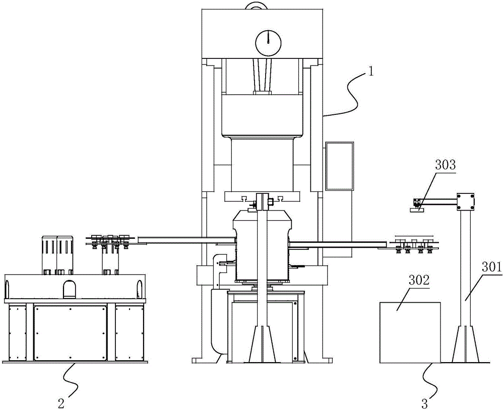
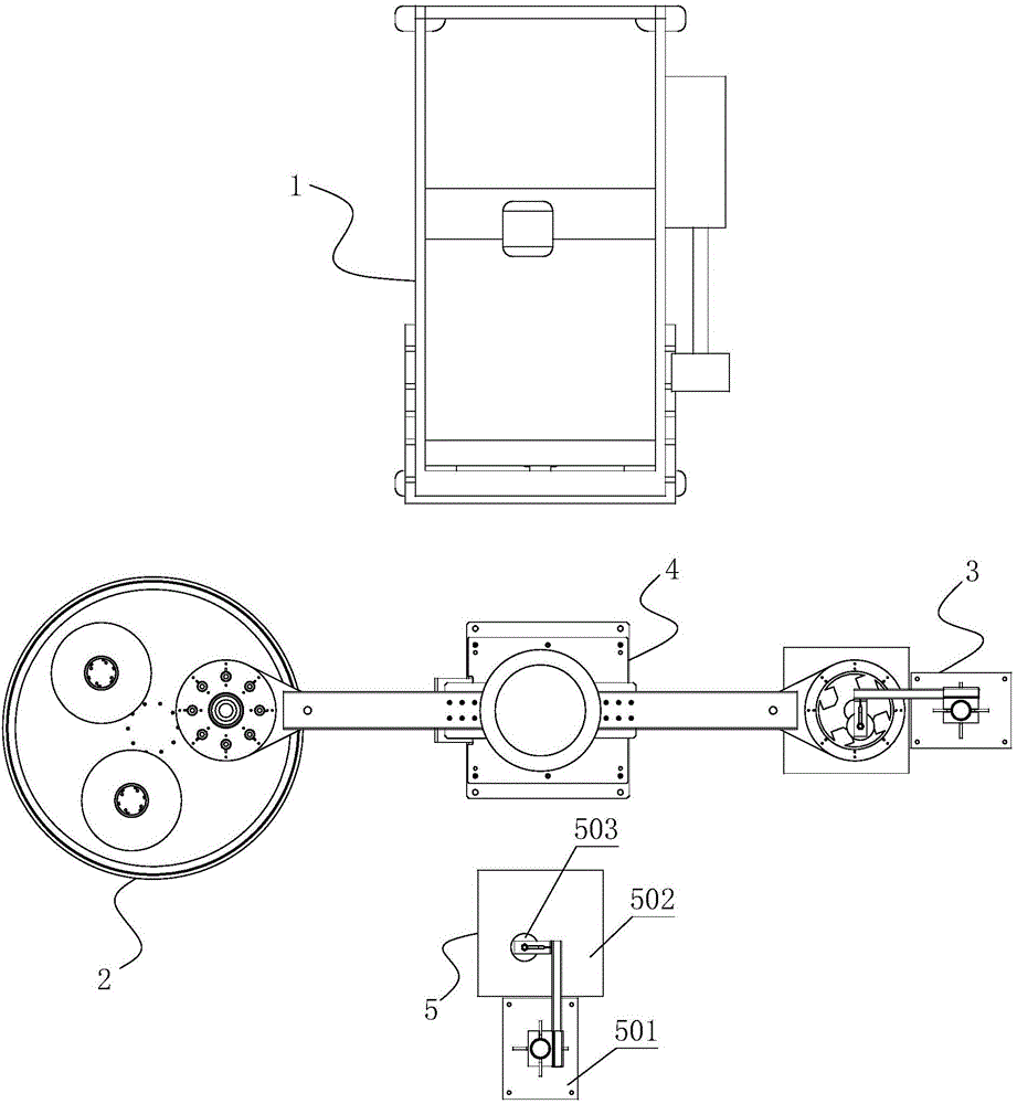
[0025] Please refer to Figure 1 to Figure 3 as shown, figure 1 It is a front view of a silicon steel sheet stamping production line of the present invention; figure 2 It is a top view of a silicon steel sheet stamping production line of the present invention; image 3 It is a structural schematic diagram of the stamping transfer robot of the present invention.

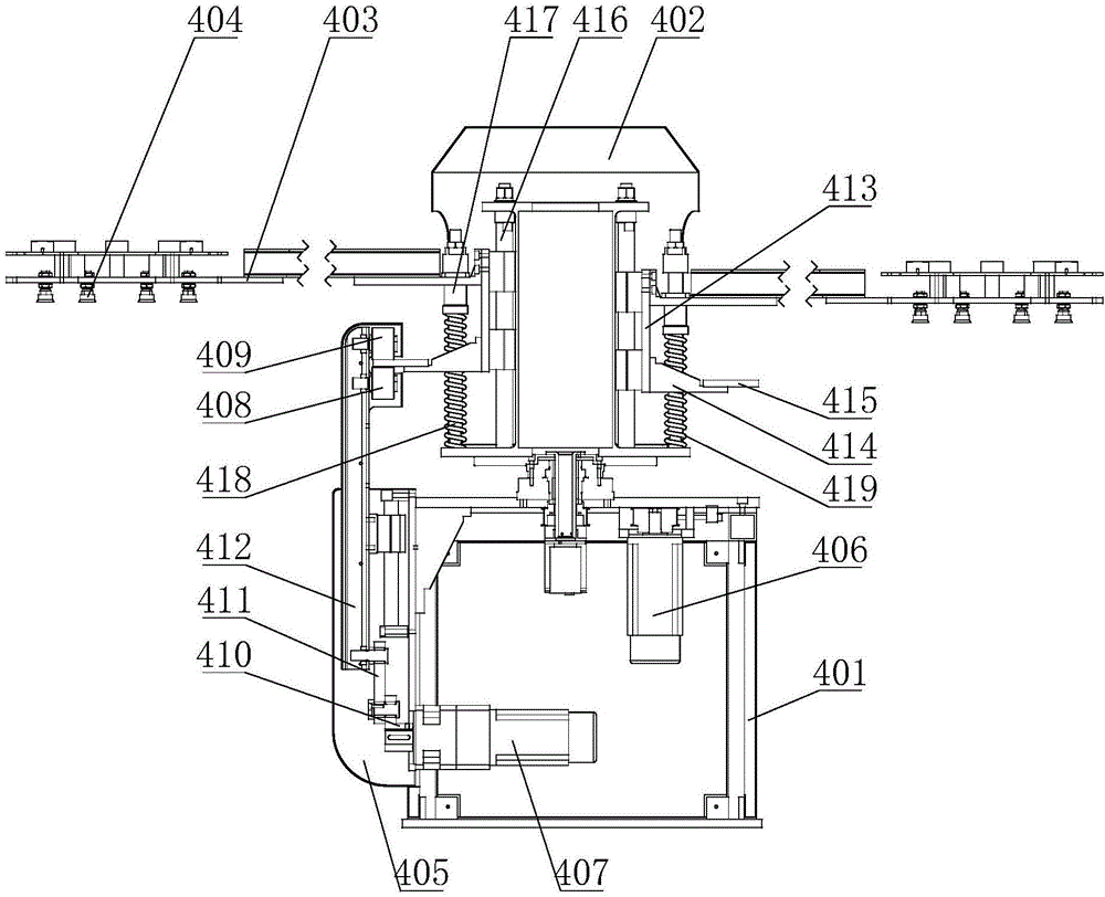
[0026] In this embodiment, a silicon steel sheet stamping production line includes a stamping transfer robot 4 and a loading station, a stamping station, a blanking station, and a waste station arranged around the stamping transfer robot 4. The material station, the stamping station, the bl...


PUM


Abstract

The invention discloses a silicon steel plate stamping production line. The silicon steel plate stamping production line comprises a stamping transfer robot as well as a loading station, a stamping station and an unloading station which are arranged at the periphery of the stamping transfer robot; the loading station, the stamping station and the unloading station are sequentially distributed in a circumferential direction; a multi-station loading device is arranged on the loading station; a punch is arranged on the stamping station; a stamping mould is mounted on the punch; the stamping mould comprises an upper mould and a lower mould; a sucking device used for sucking the silicon steel plate is arranged on the upper mould; the unloading device is arranged on the unloading station; the stamping transfer robot comprises a rack; the rack is rotatably connected with a rotary frame; the rotary frame is driven by a rotary motor; at least one mechanical arm is arranged on the rotary frame; and a clamping device used for sucking the silicon steel plate is mounted on the mechanical arm. The silicon steel plate stamping production line is simple in structure and is reasonable in arrangement; and the stamping transfer robot rotates in a one-way mode, so that the mechanical arm does not need to return, and therefore, quick loading and unloading for the silicon steel plate can be realized.

Description

technical field [0001] The invention relates to a production line, in particular to a silicon steel sheet stamping production line. Background technique [0002] Silicon steel sheet is a kind of silicon-iron soft magnetic alloy with extremely low carbon content. It has excellent electromagnetic properties and is an indispensable and important magnetic material in the electric power, telecommunications and instrument industries. [0003] At present, silicon steel sheets need to be stamped during production. The existing stamping production line for silicon steel sheets is not properly arranged. The stamping and handling robot returns to its position after loading, and then takes out the materials after the stamping is completed. The entire process takes a long time. Longer, its efficiency is lower, thus, urgently need to solve. Contents of the invention [0004] The object of the present invention is to address the above problems and provide a silicon steel sheet stamping ...

Claims


Application Information

Patent Timeline
Patent Type & Authority Applications(China)
IPC IPC(8): B21D22/00B21D43/00B21D43/18B21D45/06
CPCB21D22/00B21D43/00B21D43/18B21D45/06
Inventor 周利锋闫东张宁峰
Owner WUXI IDO SCI & TECH CO LTD
Why Eureka
Try Eureka