Basket ring spring hook butt welding machine

A spring hook, butt welding machine technology, applied in welding equipment, resistance welding equipment, metal processing equipment and other directions, can solve the problems of inconvenient positioning of the spring hook, low production efficiency, insufficient welding seam strength, etc., and achieve stable and reliable solder joints. Low cost and good quality

Active Publication Date: 2017-01-11
LIRUIBAO SPORTS EQUIP WUJIANG
View PDF8 Cites 11 Cited by
  • Summary
  • Abstract
  • Description
  • Claims
  • Application Information

AI Technical Summary

Problems solved by technology

[0002] There are 12 spring hooks on each ring, which need to be connected. Today’s production method is generally manual processing. During processing, because the ring is formed by thick steel wires and the surface is curved, the positioning of the spring hooks is inconvenient. And manual spot welding, the size of the solder joints is different, prone to false welding, the weld strength is not enough and the production efficiency is low

Method used


Image

  • Basket ring spring hook butt welding machine
  • Basket ring spring hook butt welding machine
  • Basket ring spring hook butt welding machine

Examples


Embodiment 1

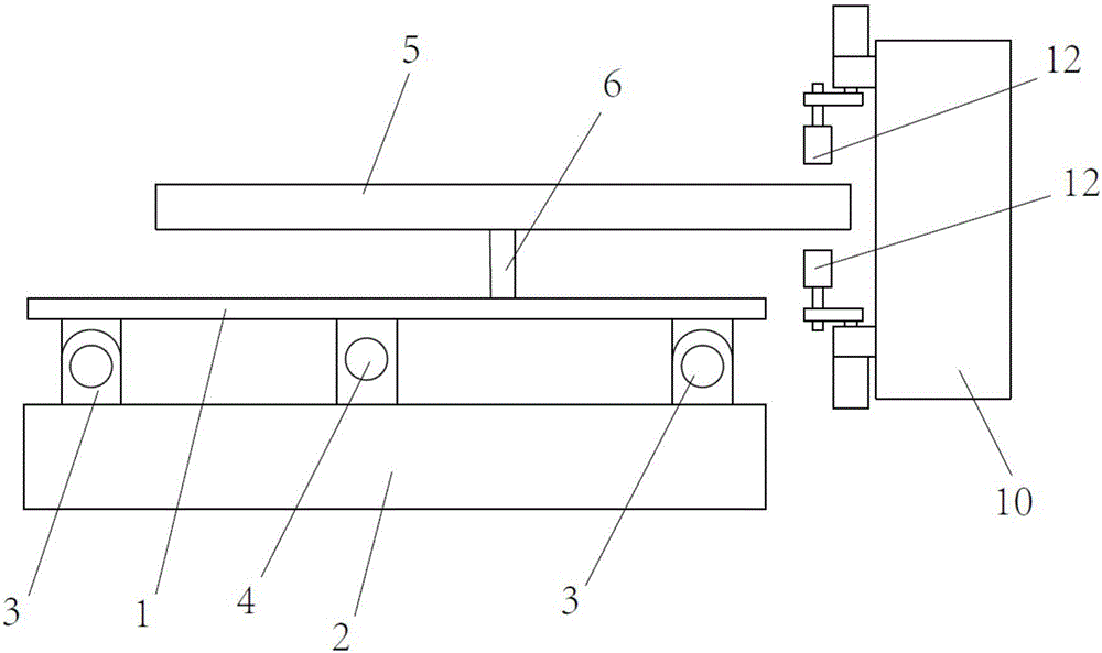
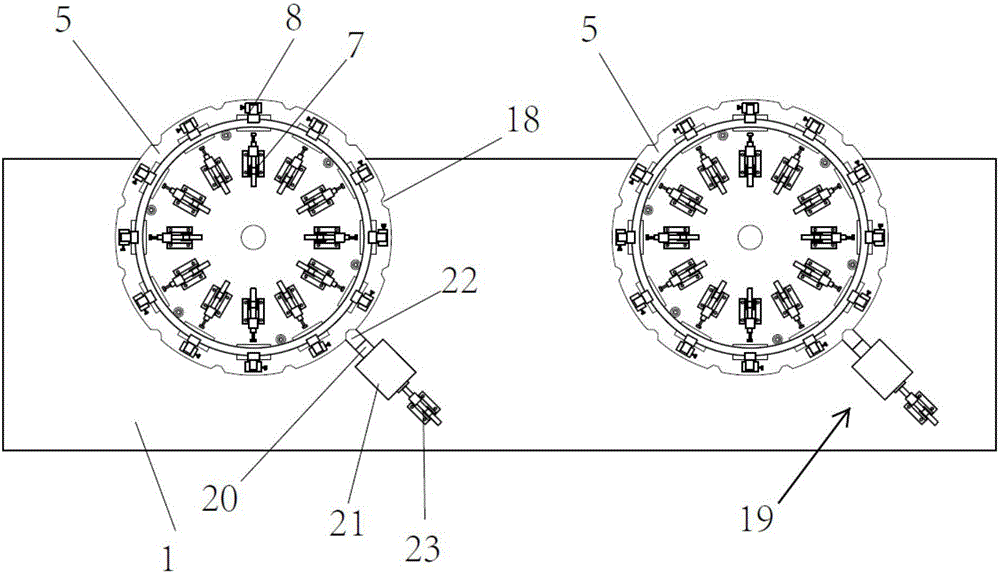
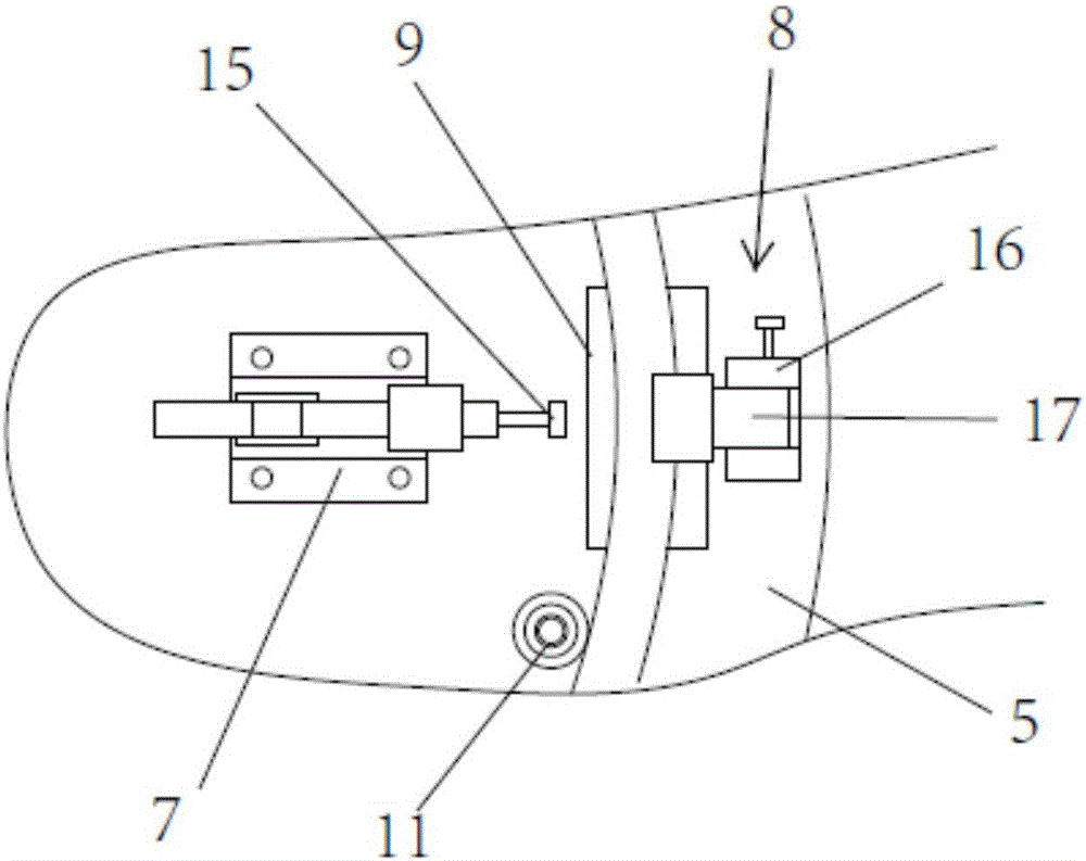
[0029] refer to Figure 1 to Figure 5 As shown, a butt welding machine for a basket spring hook includes a bottom plate 1, the bottom plate is arranged on a mobile support 2, a first guide assembly 3 and a transmission mechanism 4 are arranged between the bottom plate and the mobile support, and the surface of the bottom plate is arranged along the moving direction. There are two loading discs 5, the loading discs are connected to the bottom plate through the rotating assembly 6, a number of first quick clamps 7 are arranged on the surface of the loading disc along the same circumference, and the surface between the several first quick clamps and the outer circumference of the loading disc A number of abutment positioning parts 8 are also provided along the same circumference. The first quick clamp and the abutment positioning part cooperate to clamp the spring hook. There is a butt welding avoidance groove 9, and a butt welding machine 10 is arranged on one side of the loadin...

Embodiment 2

[0037] The difference between the second embodiment and the first embodiment is that the rotating component is an indexing plate, and the rotation can be easily realized by controlling the indexing plate, so as to achieve better automation performance and reduce labor force.


PUM


Abstract

The invention discloses a basket ring spring hook butt welding machine which comprises a base plate. The base plate is arranged on a mobile support. A first guide assembly and a transmission mechanism are arranged between the base plate and the mobile support, and two loading discs are arranged on the surface of the base plate in the moving direction. The loading discs are connected with the base plate through a rotating assembly, a plurality of first quick clamps are arranged on the surfaces of the loading discs along the same circumference, and a plurality of butting positioning parts are further arranged between the edges of the plurality of first quick clamps and the outer circumferences of the loading discs along the same circumference. The first quick clamps and the butting positioning parts are matched with clamping spring hooks, the loading discs between the first quick clamps and the corresponding butting positioning parts are provided with butt welding avoiding grooves, and the butt welding machine is arranged on one side of each loading disc. The basket ring spring hook butt welding machine can effectively position the spring hooks and is high in welding efficiency and good in quality.

Description

technical field [0001] The invention relates to the field of sports equipment preparation, in particular to a hoop spring hook butt welding machine. Background technique [0002] There are 12 spring hooks on each ring, which need to be connected. Today’s production method is generally manual processing. During processing, because the ring is formed by thick steel wires and the surface is curved, the positioning of the spring hooks is inconvenient. And manual spot welding, the size of the solder joints is different, prone to false welding, the weld strength is not enough and the production efficiency is low. Contents of the invention [0003] The purpose of the present invention is to overcome the above problems in the prior art and provide a butt welding machine for the spring hook of the basket ring. The present invention can effectively position the spring hook, and the welding efficiency is high and the quality is good. [0004] In order to achieve the above-mentioned ...

Claims


Application Information

Patent Timeline
Patent Type & Authority Applications(China)
IPC IPC(8): B23K11/00B23K11/36
CPCB23K11/00B23K11/002B23K11/36
Inventor 姜金停史跃飞吴文杰崔嫘李春磊兰远远朱洁明何海娟尹传强罗卫庆崔黎静万凤珍余深海
Owner LIRUIBAO SPORTS EQUIP WUJIANG
Why Eureka
Try Eureka