Circle center aligning method for aviation revolution part machining basic circle

A technology for machining parts and machining benchmarks, which is applied in the field of center alignment of the benchmark circle for machining of aviation rotary parts to achieve the effect of reducing adjustment time, accurate results and high accuracy.

Active Publication Date: 2017-01-11
杭州天扬机械有限公司
View PDF7 Cites 30 Cited by
  • Summary
  • Abstract
  • Description
  • Claims
  • Application Information

AI Technical Summary

Problems solved by technology

[0003] The technical problem to be solved by the present invention is to provide an alignment method suitable for various aviation rotary parts, which can accurately and efficiently solve the datum center alignment of thin-walled deformed parts and the large roundness of the datum circle of the machined parts. Positive problem

Method used


Image

  • Circle center aligning method for aviation revolution part machining basic circle
  • Circle center aligning method for aviation revolution part machining basic circle
  • Circle center aligning method for aviation revolution part machining basic circle

Examples


Embodiment 1

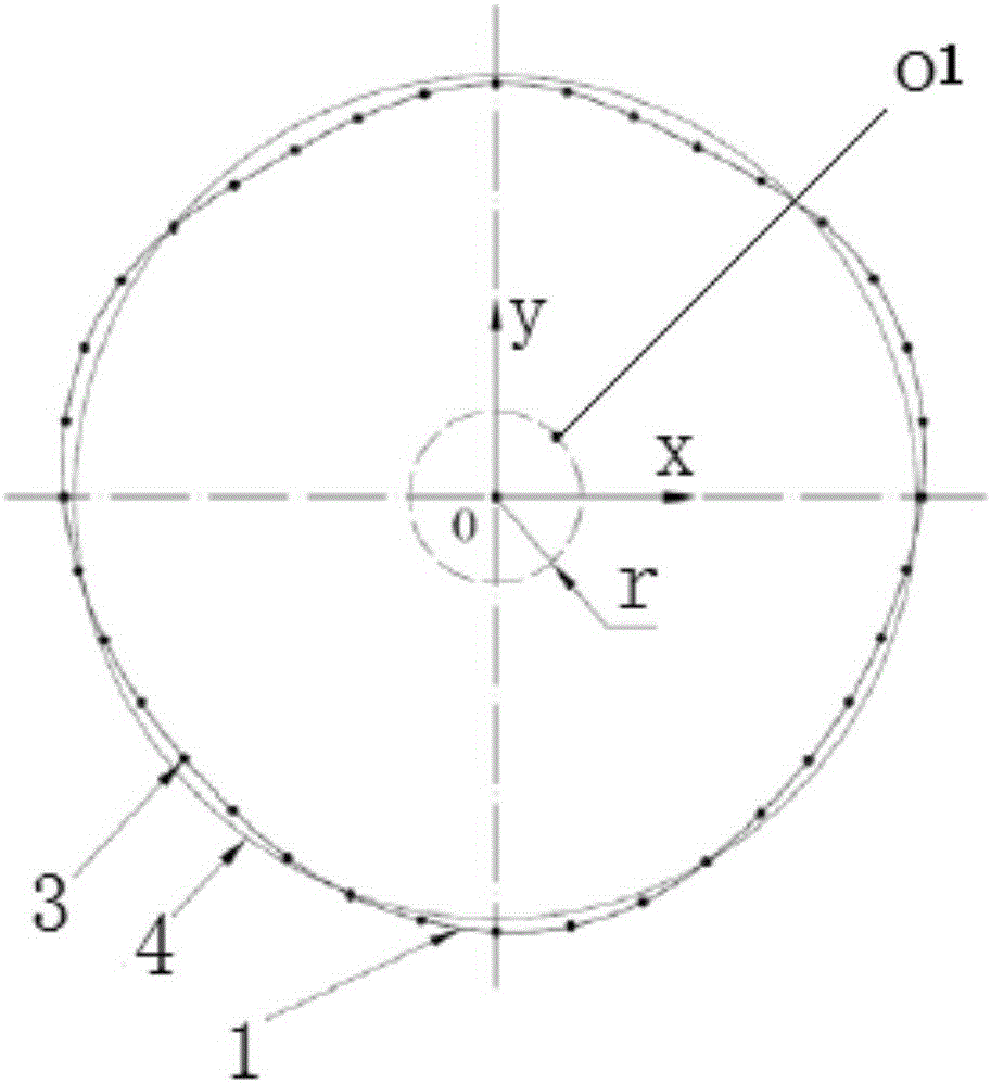
[0018] Example 1 as image 3 As shown, this embodiment is described with a method for center alignment of a circular part machining reference circle, and the specific steps include:

[0019] A. Initially assemble the ring parts, set the alignment coordinate system SCS, and the machine tool has returned to zero according to the alignment coordinate system SCS (the coordinate origin of the measurement program coincides with the center of the machine tool rotary table); place the parts on the machine tool to rotate The center of the workbench, so that the center of the reference circle roughly coincides with the center of the rotary table of the machine tool, that is, the center O1 of the part processing reference circle roughly coincides with the rotation center O of the machine tool table (four points are evenly distributed on the circumference of the part, and two symmetrical points are connected to the machine tool). The difference of the distance between the center of rotati...


PUM


Abstract

The invention relates to a circle center aligning method for an aviation revolution part machining basic circle. According to the aligning method, multi-point measurement is conducted on the circumference of the basic circle, a least square method principle is adopted for calculating a measuring point, coordinates of the circle center of the basic circle are obtained, and therefore the accurate position of the basic center of a machined part in a machine tool rotation table is quantized. Compared with traditional circumference four-point alignment or circumference jerk value alignment, the method is more scientific in principle and more accurate in result.

Description

technical field [0001] The invention relates to the field of machining aviation rotary parts, in particular to a method for correcting the center of a machining reference circle for aviation rotary parts. Background technique [0002] In the process of machining aviation rotary parts, it is first necessary to align the reference center point of the part. The traditional alignment method is to measure the circumference of the machining reference of the processed part by means of a machine tool. There are two main types. The first method is to perform alignment by the runout of the machining reference circle, and the part has been aligned when the specified runout is not greater than a certain value. The second is to measure the four symmetrical points on the circumference of the machining reference circle 1 to adjust the distance difference between the two symmetrical points and the center of the rotary table of the machine tool (the distance difference between point A to the...

Claims


Application Information

Patent Timeline
Patent Type & Authority Applications(China)
IPC IPC(8): B23Q17/22G01B21/00
CPCB23Q17/22G01B21/00
Inventor 李鹏郭世栋
Owner 杭州天扬机械有限公司
Why Eureka
Try Eureka