
Control system of 3D printing device

A control system, 3D printing technology, applied in general control system, control/regulation system, program control and other directions, can solve the problems affecting printing quality, speed and accuracy, and achieve the effect of low cost, high precision and reasonable design

Inactive Publication Date: 2017-01-11
HENAN LONGJING TECH
View PDF5 Cites 4 Cited by
  • Summary
  • Abstract
  • Description
  • Claims
  • Application Information

AI Technical Summary

Problems solved by technology

[0002] Most of the 3D printers currently in use use the open source REPRAP 3D printer control system solution, which uses the timer output pulse of the MCU to control the motor operation mode. The speed and accuracy of this control system are not high during use, which seriously affects In order to improve the printing quality, it is of great significance to provide a control system for 3D printing devices with reasonable design, convenient use, fast printing speed and high precision.

Method used


Image

  • Control system of 3D printing device

Examples


Embodiment 1

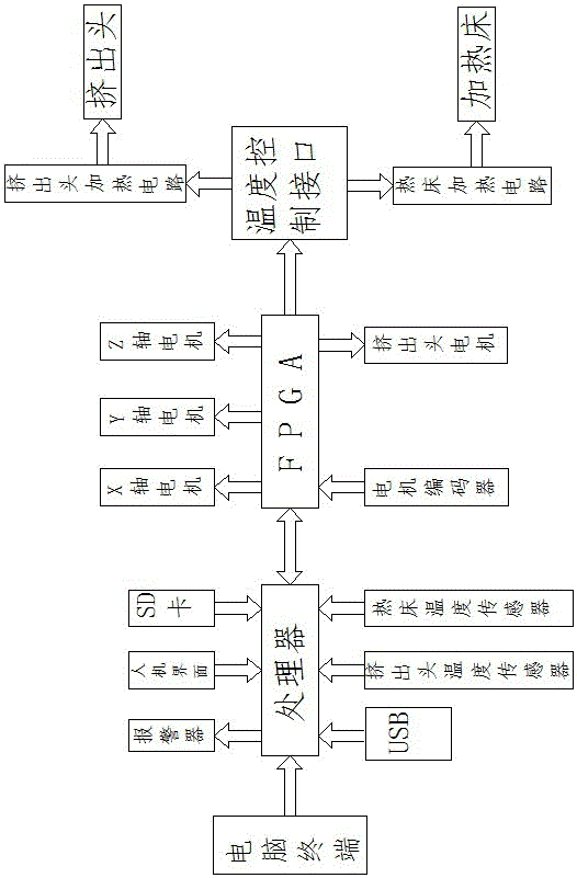
[0014] like figure 1 As shown, a control system of a 3D printing device includes a computer terminal, the computer terminal is connected to a processor through a data line, and the input end of the processor is respectively connected to a USB interface and a man-machine interface through a signal line , SD card interface, extrusion head temperature sensor and hot bed temperature sensor, the output end of processor is respectively connected with alarm and FPGA by signal line, and the output end of described FPGA is respectively connected with X-axis motor, Y-axis motor, The Z-axis motor and the temperature control interface, the temperature control interface is respectively connected to the extrusion head heating circuit and the hot bed heating circuit, the extrusion head heating circuit is connected to the extrusion head, and the hot bed heating circuit is connected to There is a heated bed, and the input of the FPGA is connected to a motor encoder.

[0015] The present inven...

Embodiment 2

[0017] like figure 1 As shown, a control system of a 3D printing device includes a computer terminal, the computer terminal is connected to a processor through a data line, and the input end of the processor is respectively connected to a USB interface and a man-machine interface through a signal line , SD card interface, extrusion head temperature sensor and hot bed temperature sensor, the output end of processor is respectively connected with alarm and FPGA by signal line, and the output end of described FPGA is respectively connected with X-axis motor, Y-axis motor, The Z-axis motor and the temperature control interface, the temperature control interface is respectively connected to the extrusion head heating circuit and the hot bed heating circuit, the extrusion head heating circuit is connected to the extrusion head, and the hot bed heating circuit is connected to There is a heating bed, and the input end of FPGA is connected with a motor encoder, and the processor is an ...


PUM


Abstract

The invention relates to a control system of a 3D printing device. The control system comprises a computer terminal; the computer terminal is connected with a processor through a data line; an input end of the processor is separately connected with a USB interface, a human-computer interface, an SD card interface, an extrusion head temperature sensor and a hot bed temperature sensor through signal lines; an output end of the processor is separately connected with an alarm and an FPGA through signal lines; an output end of the FPGA is separately connected with an X-axis motor, a Y-axis motor, a Z-axis motor and a temperature control interface; the temperature control interface is separately connected with an extrusion head heating circuit and a hot bed heating circuit; the extrusion head heating circuit is connected with an extrusion head; the hot bed heating circuit is connected with a heating bed; and an input end of the FPGA is connected with a motor coder. The control system has the advantages of a reasonable design, convenient use, high printing speed and high precision.

Description

technical field [0001] The invention belongs to the technical field of 3D printer equipment, and in particular relates to a control system of a 3D printing device. Background technique [0002] Most of the 3D printers currently in use use the open source REPRAP 3D printer control system solution, which uses the timer output pulse of the MCU to control the motor operation mode. The speed and accuracy of this control system are not high during use, which seriously affects In order to improve the printing quality, it is of great significance to provide a control system for 3D printing devices with reasonable design, convenient use, fast printing speed and high precision. Contents of the invention [0003] The object of the present invention is to provide a control system of a 3D printing device with reasonable design, convenient use, fast printing speed and high precision in order to overcome the deficiencies of the prior art. [0004] The object of the present invention is ...

Claims


Application Information

Patent Timeline
Patent Type & Authority Applications(China)
IPC IPC(8): B29C67/00G05B19/042B33Y50/02
CPCG05B19/042B33Y50/02
Inventor 孔艳阳张宏山朱业革
Owner HENAN LONGJING TECH
Learn More