Automobile relay valve

A technology for relay valves and automobiles, which is applied in the direction of brakes, brake components, vehicle components, etc. It can solve the problems of unstable air flow at the air intake, insufficient braking force, and filter blockage, etc., to ensure smoothness and stability, The effect of reducing the risk of clogging and increasing the effective area

Pending Publication Date: 2017-01-11
ZHEJIANG VIE SCI & TECH
View PDF5 Cites 5 Cited by
  • Summary
  • Abstract
  • Description
  • Claims
  • Application Information

AI Technical Summary

Problems solved by technology

However, since the channel at the air inlet is very small, the effective area of ​​the filter is also very small. When used in a relatively harsh environment, it is very likely that some or all of the filter will be blocked, making the air flow at the air inlet unstable, resulting in Serious situations such as braking delay and insufficient braking force; and due to the narrow space between the air inlet and the filter screen, it is very difficult to assemble the filter screen during installation

Method used


Image

  • Automobile relay valve
  • Automobile relay valve
  • Automobile relay valve

Examples


Embodiment 1

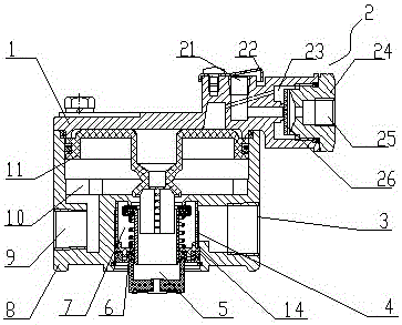
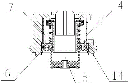
[0022] Such as figure 1 As shown, the automobile relay valve includes an upper valve body 1, a lower valve body 8 and a relay piston 11, the lower valve body 8 is provided with an air inlet 3 and an air outlet 9, and the air inlet 3 and the A piston assembly is provided between the air outlets 9; the upper valve body 1 is provided with a control port 2, and a filter screen 4 is provided in the valve body chamber 7, and the filter screen 4 is cylindrical and a piston The assembly is wrapped in the filter screen 4; a limit step 14 is provided between the filter screen 4 and the piston assembly; the lower valve body 8 is provided with a valve body chamber 7 and a relay piston chamber 10, and the described The valve body chamber 7 communicates with the relay piston chamber 10; the air inlet 3 communicates with the valve body chamber 7, and the gas outlet 9 communicates with the relay piston chamber 10; the gas enters from the air inlet 3 and passes through the valve The body cham...

Embodiment 2

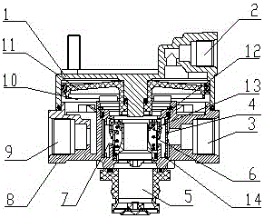
[0025] Such as figure 2 The difference between the shown automobile relay valve and the first embodiment is that the piston assembly includes a spring 6, a spring seat and a cup 13, and the cup 13 is ring-shaped; one end of the spring 6 is connected to the On the spring seat, the other end is connected with the leather cup 13. The lower valve body 8 also includes a valve seat 12. In a natural state, the leather cup 13 is in sealing contact with the valve seat 12 under the action of the spring 6. The control port 2 A two-way valve is provided to replace the diaphragm of the first embodiment. A sealing ring is provided between the valve seat 12 and the lower valve body 8, and a one-way valve is used to replace the diaphragm structure, so the performance is more reliable.

[0026] The automobile relay valve mentioned above reduces the water vapor and impurities entering the valve body, greatly reduces the failure rate of the gas circuit, and prolongs the service life of the valv...


PUM


Abstract

The invention relates to an automobile braking system, and particularly discloses an automobile relay valve. The automobile relay valve comprises an upper valve body and a lower valve body, wherein the lower valve body is provided with an air inlet, an air outlet and a valve body chamber; a relay piston chamber is arranged between the upper valve body and the lower valve body; an air inlet hole communicates with the valve body chamber; the valve body chamber communicates with the relay piston chamber; a piston assembly is arranged in the valve body chamber; a filter screen is arranged in the lower valve body; the filter screen is in a tube shape; the piston assembly is wrapped in the filter screen. The automobile relay valve disclosed by the invention has the advantages that particulate matters such as dust can be effectively prevented from entering the valve body. Compared with the condition of installing the filter screen at the air inlet part, the effective area of the filter screen is increased; the risk of filter screen blockage is reduced; meanwhile, the filter screen is arranged at the outer side of the piston assembly; the airflow circulation area in the air inlet is also increased; the air inlet blockage by dust is prevented; the air inlet smoothness and the airflow stability in the air inlet are ensured.

Description

technical field [0001] The invention relates to an automobile brake system, in particular to an automobile relay valve. Background technique [0002] During the use of the car, the water vapor generated by the air compressor and the moisture and dust particles in the atmosphere enter the relevant valve body assembly and affect the various components in the air brake system. After a long time, a large amount of impurities and rusty substances will be produced. Thus affecting the cleanliness of the pipeline of the whole vehicle, and in severe cases, affecting the braking performance of the whole vehicle. [0003] The Chinese invention patent with the patent number ZL200720311691.2 discloses a controllable brake relay valve. The controllable brake relay valve is provided with a filter at the air inlet, which effectively reduces the entry of water vapor, dust and other impurities into the valve body. Inside, the cleanliness of the pipeline of the whole vehicle is improved. How...

Claims


Application Information

Patent Timeline
Patent Type & Authority Applications(China)
IPC IPC(8): B60T15/18B01D35/02
CPCB01D35/02B60T15/18
Inventor 陈钢强王保松赵立城
Owner ZHEJIANG VIE SCI & TECH
Why Eureka
Try Eureka